Arithmetic instructions
412
Part III FP Instructions
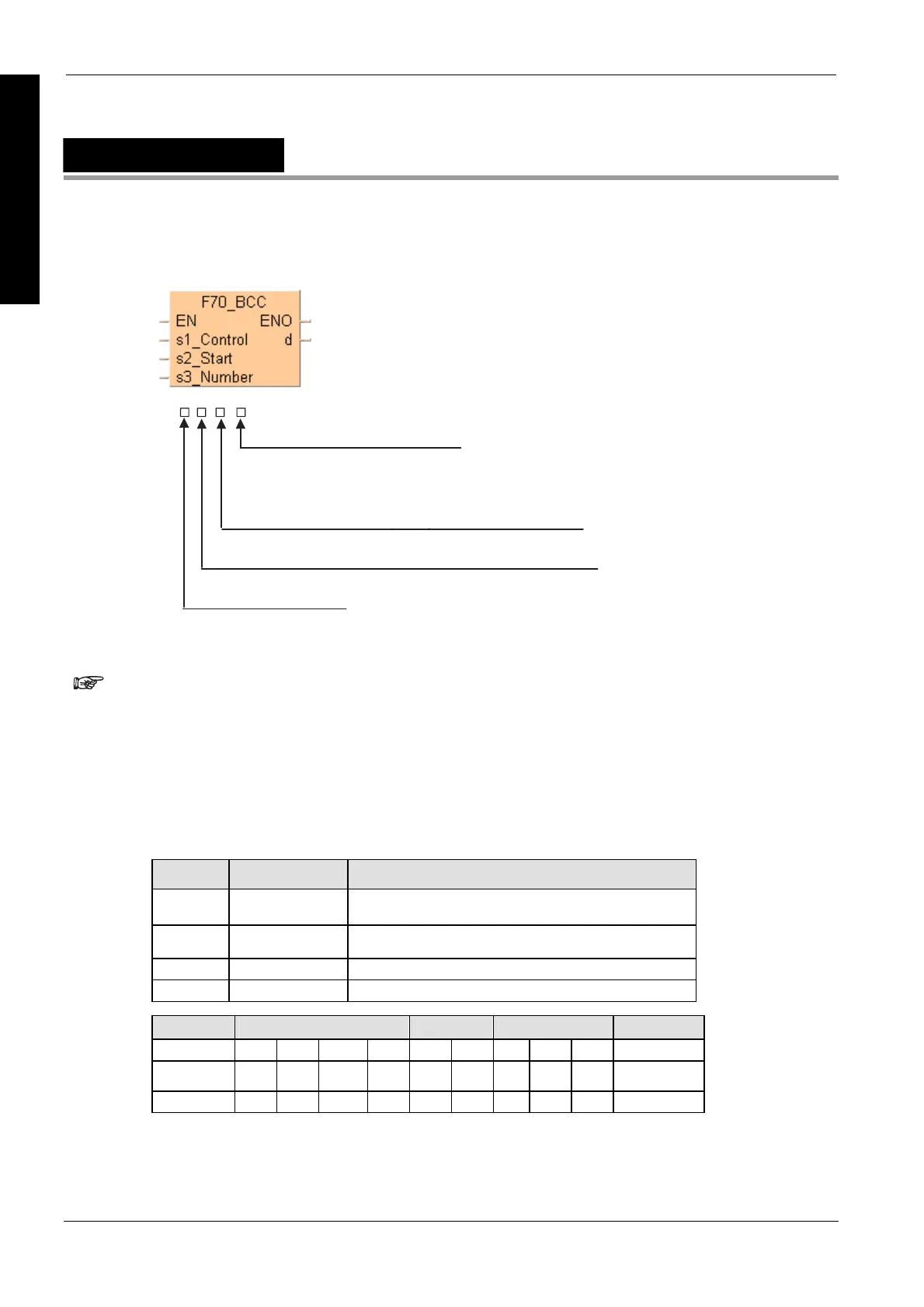
F70_BCC
Block check code calculation
16#
BCC calculation method set with “s1”
0: Addition
1: Substraction
2: Exclusive OR operation
A: CRC-16
Starting byte position for calculation (No. of bytes from “s2”)
Conversion data
0 to F
Starting byte position for storing results (No. of bytes from “d”)
0 to F
0: Binary data (CRC: 2 bytes / Not CRC: 1 byte)
1: ASCII code (2 bytes)
If CRC-16 is specified as the calculation method, ASCII code cannot be
specified for the conversion data.
PLC types
Availability of F70_BCC (see page 1326)
This instruction also exists as a P instruction (for FP2/2SH, FP3/5, FP10/10SH PLC types), which
is only executed at the rising edge of the EN trigger. Select [Insert P instruction] from the
"Instructions" pane if you require a P instruction. To facilitate reuse, the instruction then appears
under "Recently used" in the pop-up menu. Press <Ctrl>+<Shift>+<v> within the programming
area to open the list of recently used elements.
Variable Data type Function
s1 INT specifies BCC calculation method: 0 = addition, 1 =
subtraction, 2 = exclusive OR operation
s2 ANY16 starting 16-bit area to calculate BCC
s3 INT specifies number of bytes for BCC calculation
d ANY16 16-bit area for storing BCC
For Relay T/C Register Constant
s1, s3 WX WY WR WL SV EV DT LD FL dec. or hex.
s2 WX WY WR WL SV EV DT LD FL -
d - WY WR WL SV EV DT LD FL -
Description
Calculates the Block Check Code (BCC), which is used to detect errors in message transmission,
of s3 bytes of ASCII data starting from the 16-bit area specified by s2 according to the calculation
method specified by s1. The Block Check Code (BCC) is stored in the lower byte of the 16-bit area
specified by d. (BCC is one byte. The higher byte of d does not change.)
Data types
Operands

 Loading...


