Bit-shift instructions
582
Part III FP Instructions
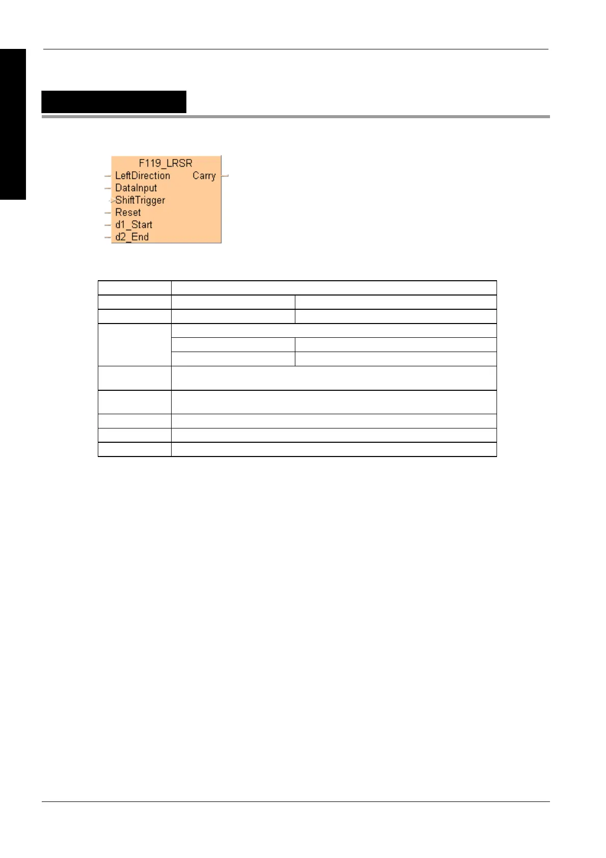
F119_LRSR
LEFT/RIGHT shift register
Left/right shift is a shift register which shifts 1 bit of the specified data area to the left (to the higher
bit position) or to the right (to the lower bit position).
LeftDirection Left/right trigger; specifies the direction of the shift-out.
LeftDirection = TRUE shifting out to the left.
LeftDirection = FALSE shifting out to the right.
Specifies the new shift-in data.
New shift-in data = TRUE: when the data input is in the TRUE-state.
DataInput
New shift-in data = FALSE: when the data input is in the FALSE-state.
ShiftTrigger
Shifts 1 bit to the left or right when the rising edge of the trigger is detected (FALSE
TRUE).
Reset Turns all the bits of the data range specified by d1_Start and d2_End to 0 if this trigger
is in the TRUE-state.
d1_Start Start of 16-bit area.
d2_End End of 16-bit area.
Carry Shifted-out bit.
Description
Shifts 1 bit of the 16-bit data range to the left or to the right.

 Loading...


