Bit-shift instructions
583
Part III FP Instructions
15
..
1211
..
87
..
43
..
0
0 0 0 1 0 0 0 1 0 0 0 1 0 0 0 1
15
..
12 11
..
87
..
43
..
0
1 0 0 0 1 0 0 0 1 0 0 0 1 1 0 0
15
..
1211
..
87
..
43
..
0
0 0 1 0 0 0 1 0 0 0 1 0 0 0 1 0
15
..
12 11
..
87
..
43
..
0
0 0 0 1
0 0 0 1
0 0 0 1 1 0 0 0
15
..
12 11
..
87
..
43
..
0
0 0 0 1 0 0 0 1 0 0 0 1 0 0 0 1
15
..
12 11
..
87
..
43
..
0
1 0 0 0 1 0 0 0 1 0 0 0 1 1 0 0
15
..
12 11
..
87
..
43
..
0
1 0 0 0 1 0 0 0 1 0 0 0 1 0 0 0
15
..
12 11
..
87
..
43
..
0
0 1 0 0 0 1 0 0 0 1 0 0 0 1 1 0
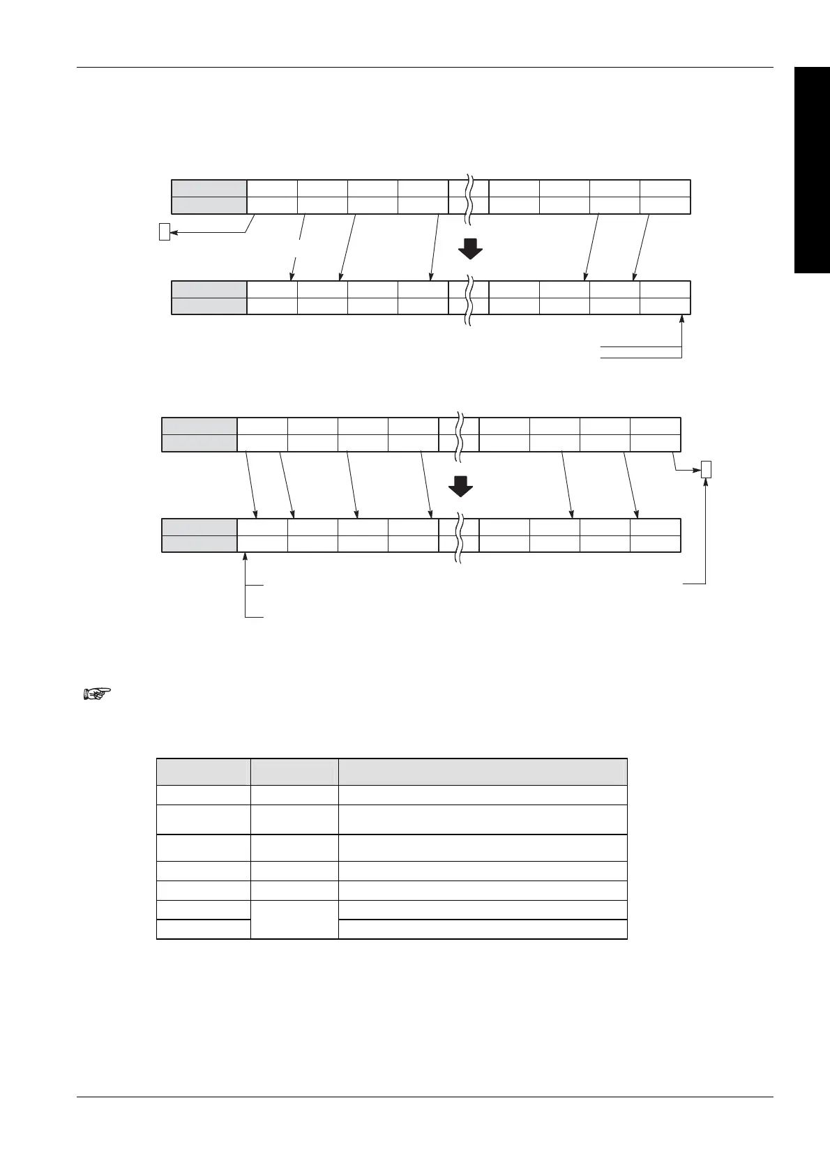
d1_Start
d1_End
d1_Start
Shifted-out bit is
transferred to
R9009 (carry flag).
ShiftTrigger: OFF, ON
When DataInput turns on, “1” is shifted into bit position 0.
ShiftTrigger: OFF, ON
When DataInput turns off, “0” is shifted into bit position 0.
d1_End
LeftDirection: OFF
When DataInput turns off, “0” is shifted into bit
position 15.
When DataInput turns on, “1” is shifted into
bit position 15.
Shifted-out bit is transferred to
R9009 (carry flag)
Bit position
LeftDirection: ON
Left shift operation
Right shift operation
Bit position
Data
Bit position
Data
Data
Bit position
Data
PLC types
Availability of F119_LRSR (see page 1320)
The variables 'd1 and d2' have to be of the same data type.
This function does not require a variable at the output "Carry".
Variable Data type Function
LeftDirection BOOL specifies direction of shift, TRUE = left, FALSE = right
DataInput BOOL shift-in data, TRUE = 1, FALSE = 0
ShiftTrigger BOOL activates shift
Reset BOOL resets data in area specified by d1 and d2 to 0
Carry BOOL bit shifted out
d1 starting 16-bit area
d2
ANY16
ending 16-bit area
Data types

 Loading...


