Analog unit instructions
1097
Part IV Tool Instructions
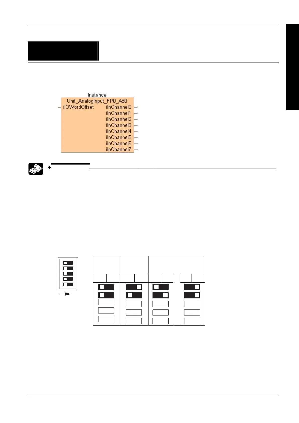
Unit_AnalogInput_
FP0_A80
Reads data from the FP0-A80 unit
REFERENCE
The online help only provides a short overview of DIP switch settings and wiring. For technical
information, please refer to the manual FP0 A/D Converter Unit ARCT1F321 manual on your FPWIN
Pro installation CD.
PLC types see see page 1333
Analog mode switch setting
Use the DIP switches at the front of the unit to set the analog channels:
Input channels, configured by DIP switches 1 and 2:
0 – 5 V,
0 – 20 mA
see note 1
-10 – +10 V -100 – +100 mV
Off On Off On Off On
Off On
ON
1
2
3
4
5
1
2
3
4
5
or
Description
This function block reads data from the input channels of the FP0-A80 unit. The result is stored as
16-bit words in the output variables iInChannel0–iInChannel7. The unit has eight channels and
supports D/A conversion.

 Loading...


