Pulse output instructions
1241
Part IV Tool Instructions
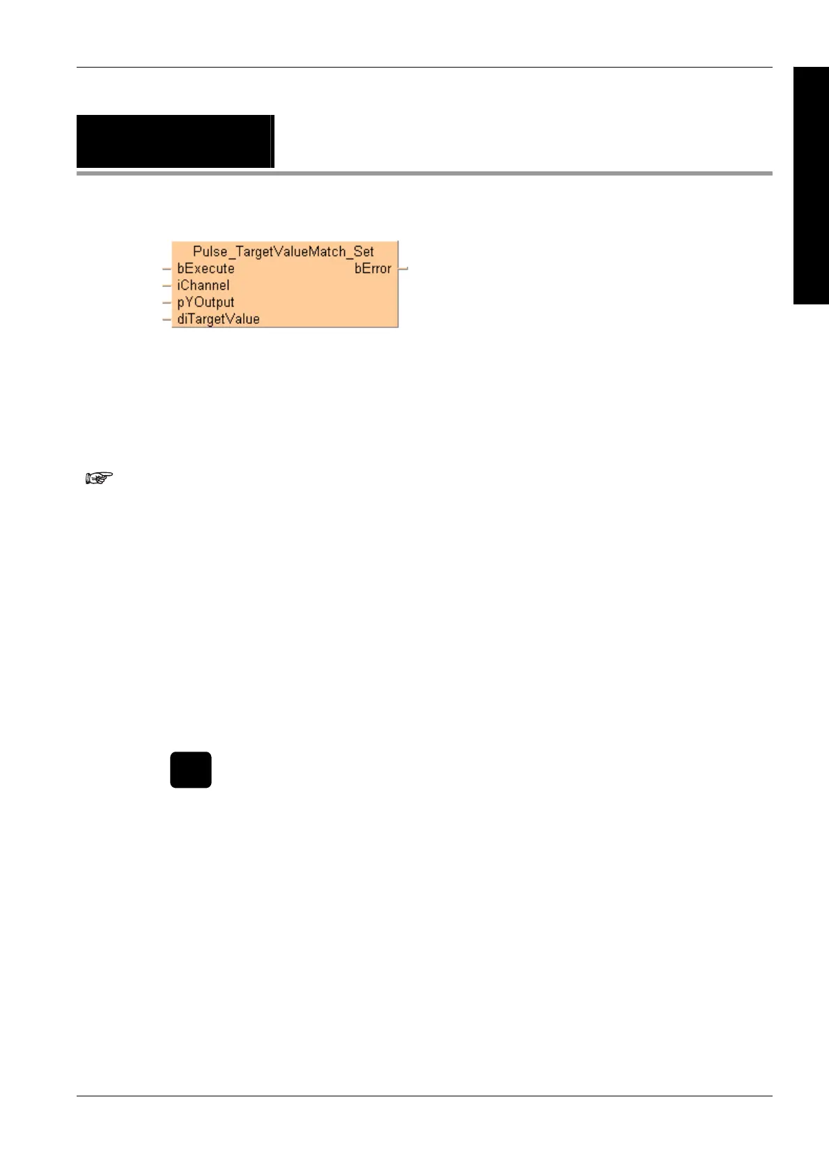
Pulse_TargetValue
Match_Set
Target value match ON (pulse output)
See also:
Pulse output tool instructions in the online help
This non-inline instruction is part of the tool instructions for pulse output. For a detailed description
of the instruction(s) used internally, please refer to the online help: F166_PulseOutput_Set (see
page 1026)
To validate the combination of channel and Y output, the compiler requires the following name
pattern for global variables:
%sPulse_TargetValueMatch_Channel%d_Y%d%s
Always use this pattern for global variables in target value match control.
Channel%d must be a pulse output channel number enabled in the system registers
Y%d must be an explicit output address supported by the PLC
FP-, FP0, FP-e:
Y0–Y7
FP- (V3.1 or higher), FP0R:
Y0–Y1F
FP-X: Y0–Y29F
%s is an optional descriptor at the beginning and the end of the pattern
Y%d must be an explicit output address supported by the PLC
FP-, FP0, FP-e:
Y0–Y7
FP- (V3.1 or higher), FP0R:
Y0–Y1F
FP-X: Y0–Y29F
%s is an optional descriptor at the beginning and the end of the pattern
Optional Fixed pattern Optional
g_b
Pulse_TargetValueMatch_ChannelA_Y11F _MotorOn
This global variable generates the code for channel A and output Y11F.
PLC types see see page 1329
Description
If the elapsed value matches the target value diTargetValue of the pulse output channel specified
by iChannel, the output relay specified by pYOutput immediately turns to TRUE.

 Loading...


