Bit-shift instructions
566
Part III FP Instructions
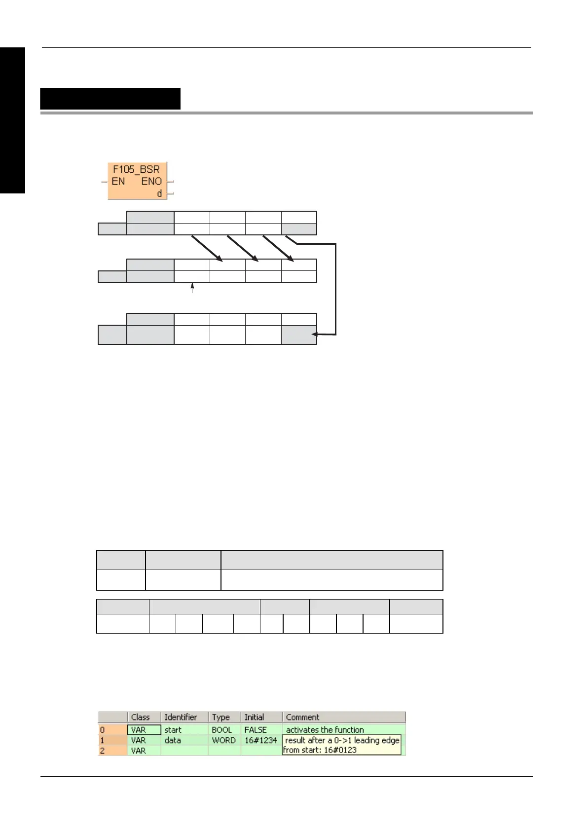
F105_BSR
Right shift of one hexadecimal digit (4 bits) of 16-bit data
000
0
·········
15 1211 8 7 4 3 0
d
·· ·· ·· ··
15 1211 8 7 4 3 0
d
·· ·· ·· ··
15 1211 8 7 4 3 0
DT9014/
DT90014
Digit 4
Hexadecimal
Bit position
Bit position
Bit position
Digit 1
Digit 2
Digit 3
Digit 2
Digit 3
Digit 4
This hexadecimal digit position becomes 0.
Digit 1
Hexadecimal
Hexadecimal
When one hexadecimal digit (4 bits) is shifted to the right,
hexadecimal digit position 0 (bit position 0 to 3) of the data specified by d is
shifted out and is transferred to the lower digit (bit position 0 to 3) of special data
register DT9014 (DT90014 for FP2/2SH and FP10/10S/10SH).
hexadecimal digit position 3 (bit position 12 to 15) of the 16-bit area specified by
d becomes 0.
This instruction is useful when the hexadecimal or BCD data is handled.
This instruction also exists as a P instruction (for FP2/2SH, FP3/5, FP10/10SH PLC types), which
is only executed at the rising edge of the EN trigger. Select [Insert P instruction] from the
"Instructions" pane if you require a P instruction. To facilitate reuse, the instruction then appears
under "Recently used" in the pop-up menu. Press <Ctrl>+<Shift>+<v> within the programming
area to open the list of recently used elements.
PLC types
Availability of F105_BSR (see page 1320)
Variable Data type Function
d ANY16 16-bit area to be shifted to the right
For Relay T/C Register Constant
d - WY WR WL SV EV DT LD FL -
Description
Shifts one hexadecimal digit (4 bits) of the 16-bit area specified by d to the right (to the lower digit
position) if the trigger EN is in the ON-state.
Data types
Operands
Example
In this example the function has been programmed in ladder diagram (LD) and structured text
(ST).The same POU header is used for all programming languages.
POU header
All input and output variables used for programming this function have been declared in the POU
header.

 Loading...


