Arithmetic instructions
449
Part III FP Instructions
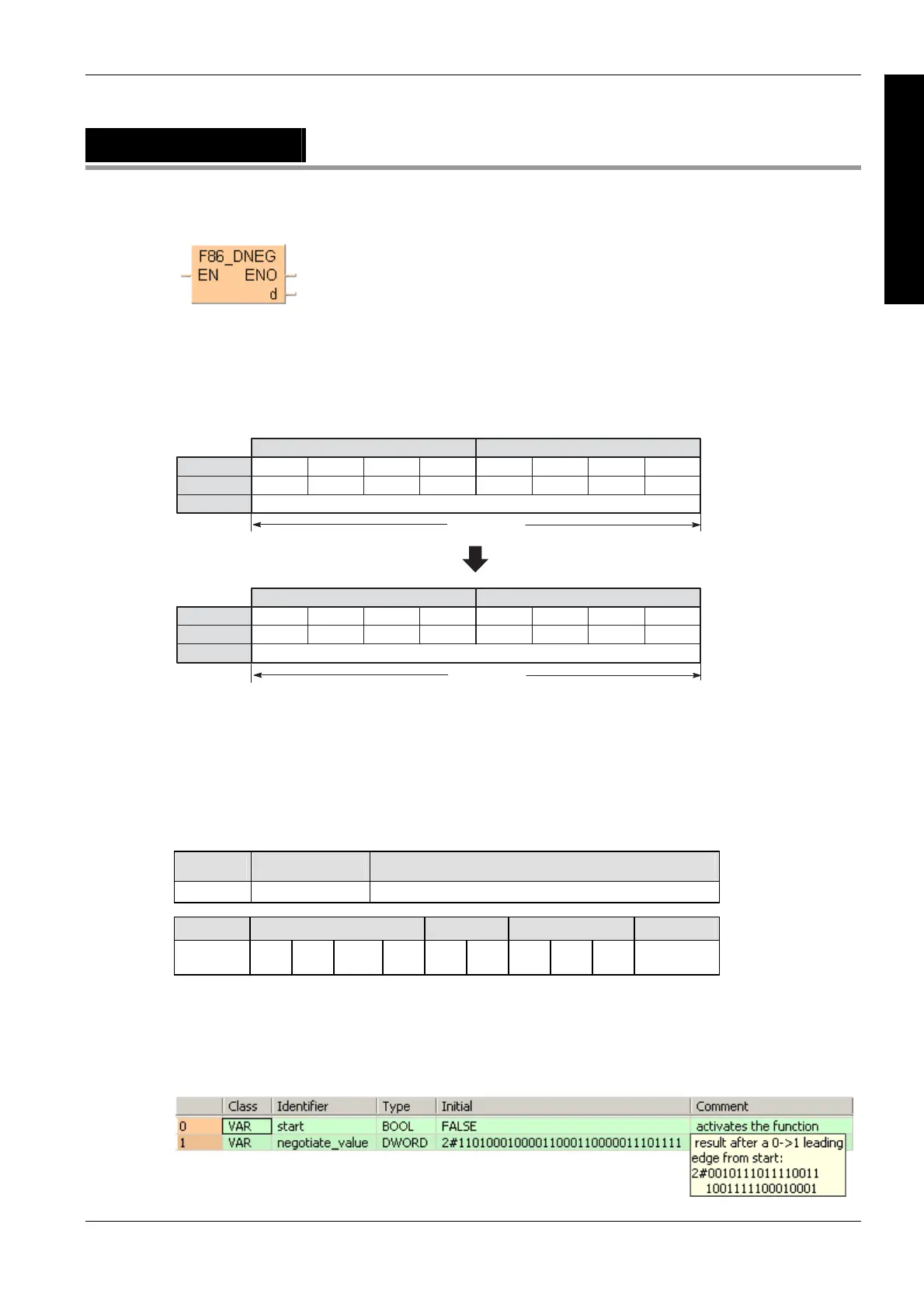
F86_DNEG
32-bit data two's complement
Two’s complement is a number system used to express positive and negative numbers in binary
format. In this system, the number becomes negative if the most significant bit (MSB) of data is 1.
Two’s complement is obtained by inverting all bits and adding 1 to the inverted result.
This instruction is useful for inverting the sign of 32-bit data from positive to negative or from
negative to positive.
·········
15
0
1211
00
8
0
7
00
4
0
3
0
0
·········
15
0
12
0
11
0
8
0
7
0
4
0
3
01
0
1
DT1 DT0
·········
15
1
1211
11
8
1
7
11
4
1
3
1
0
·········
15
1
12
1
11
1
87
1
4
1
3
10
0
1
DT1 DT0
1111111111111111
-3
000000000000000
3
start: ON
Destination
Destination
Bit position
Bit position
32-bit area
32-bit area
Binary data
Binary data
Decimal data
Decimal data
This instruction also exists as a P instruction (for FP2/2SH, FP3/5, FP10/10SH PLC types), which
is only executed at the rising edge of the EN trigger. Select [Insert P instruction] from the
"Instructions" pane if you require a P instruction. To facilitate reuse, the instruction then appears
under "Recently used" in the pop-up menu. Press <Ctrl>+<Shift>+<v> within the programming
area to open the list of recently used elements.
PLC types
Availability of F86_DNEG (see page 1326)
Variable Data type Function
d ANY32 32-bit area for storing original data and its two's complement
For Relay T/C Register Constant
d - DWY DWR DWL DSV DEV DDT DLD DFL -
Description
Takes two's complement of 32-bit data specified by d if the trigger EN is in the ON-state. Two's
complement of the original 32-bit data is stored in d.
Data types
Operands
Example
In this example the function has been programmed in ladder diagram (LD) and structured text
(ST).The same POU header is used for all programming languages.
POU header
All input and output variables used for programming this function have been declared in the POU
header.

 Loading...


