Bit-shift instructions
594
Part III FP Instructions
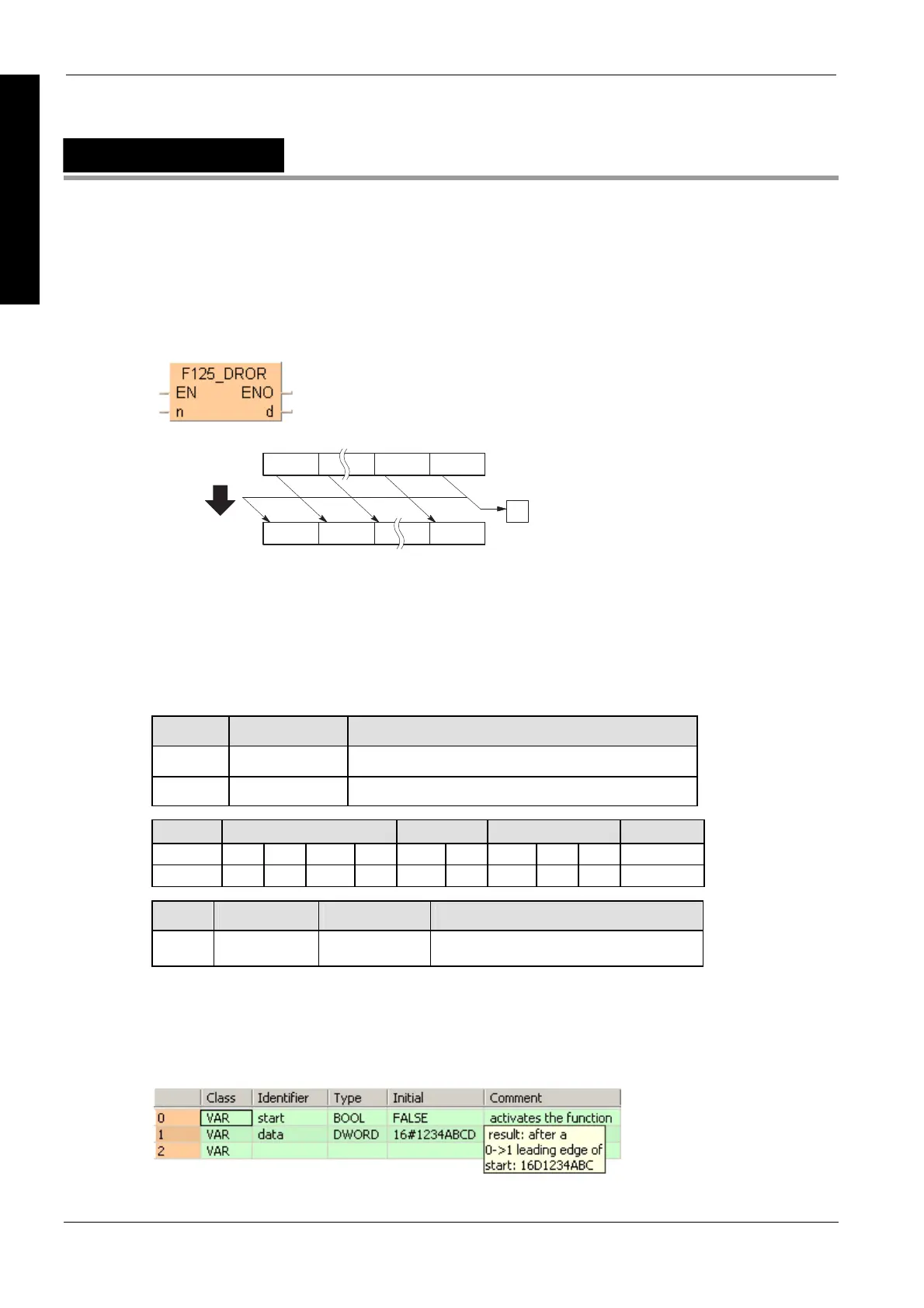
F125_DROR
32-bit data right rotate
1 0 1 0 1 1 0 0 1 0 1 1
31 0
1 0 1 1 1 0 1 0 1 1 0 0
28 27 8 7 4 3
· · ·
Carry
flag
data
start: ON
data
This instruction also exists as a P instruction (for FP2/2SH, FP3/5, FP10/10SH PLC types), which
is only executed at the rising edge of the EN trigger. Select [Insert P instruction] from the
"Instructions" pane if you require a P instruction. To facilitate reuse, the instruction then appears
under "Recently used" in the pop-up menu. Press <Ctrl>+<Shift>+<v> within the programming
area to open the list of recently used elements.
PLC types
Availability of F125_DROR (see page 1320)
Variable Data type Function
n INT number of bits to be rotated (range: 0 to 255)
d ANY32 32-bit area
For Relay T/C Register Constant
n WX WY WR WL SV EV DT LD FL dec. or hex.
d - DWY DWR DWL DSV DEV DDT DLD DFL -
No. IEC address Set If
R9009 %MX0.900.9 for an instant the bit at position n - 1 of d has the value
1.
Description
The function rotates the value at output d to the right. The number of bits at output d to be rotated
to the right is specified by the value assigned at input n. This shift can lie between 0 and 255 (only
the lower value byte of n is effective). Right rotate means that the bits shifted out of bit position 0
(LSB) are shifted via bit position 31 (MSB) into the value at output d. When input n = 0, no rotation
takes place. When at input n > 32, the same result is achieved as with a number n < 32: e.g. n =
32 produces the same result as when n = 0; n = 33 the same as n = 1. The bit at position n - 1 (the
last bit shifted out to the right) is simultaneously stored in special internal relay R9009 (carry flag)
so that it can be evaluated accordingly.
Data types
Operands
Error flags
Example
In this example, the same POU header is used for all programming languages. For an example
using IL (instruction list), please refer to the online help.
POU header
All input and output variables used for programming this function have been declared in the POU
header.

 Loading...


