Basics
28
Special internal relays can only be read.
1.1.4 Timers and Counters
Timers and Counters use one common memory and address area.
Define in system registers 5 and 6 how the memory area is to be divided between timers and counters and
which timers/counters are supposed to be holding or non-holding. Holding means that even after a power failure
all data will be saved, which is not the case in non-holding registers.
Entering a number in system register 5 means that the first counter is defined. All smaller numbers define
timers.
For example, if you enter zero, you define counters only. If you enter the highest value possible, you define
timers only.
In the default setting the holding area is defined by the start address of the counter area. This means all timers
are holding and all counters are non-holding. You can of course customize this setting and set a higher value for
the holding area, which means some of the timers, or if you prefer, all of them can be defined as holding.
In addition to the timer/counter area, there is a memory area reserved for the set value (SV) and the elapsed
value (EV) of each timer/counter contact. The size of both areas is 16 bits (WORD). In the SV and EV area one
INTEGER value from 0 to 32,767 can be stored.
Timer/Counter No. SV EV Relay
TM0 SV0 EV0 T0
.
.
.
.
.
.
.
.
.
.
.
.
TM99 SV99 EV99 T99
CT100 SV100 EV100 C100
.
.
.
.
.
.
.
.
.
.
.
.
While a timer or counter is being processed, the respective acual value can be read and under certain
conditions be edited.
After changing the settings in system register 5, do not forget to adjust
the addresses of the timers/counters in your PLC program because they
correspond to the TM/CT numbers.
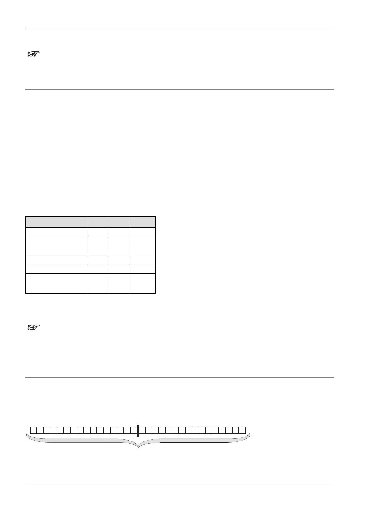
1.1.5 Data Registers (DT)
Data registers have a width of 16 bits. You can use them, for example, to write and read constants/parameters.
If an instruction requires 32 bits, two 16-bit data registers are used. If this is the case, enter the address of the
first data register with the prefix DDT instead of DT. The next data register (word) will be used automatically (for
more information, please refer to addresses (see page 30)).
DT2
DT1
2nd word
1st word
32 bit data register
Data registers can be holding or non-holding. Holding means that even after a power failure all data will be

 Loading...


