Arithmetic instructions
417
Part III FP Instructions
F300_BSIN
BCD type Sine operation
BCD values for input s lie in the area from 0° to 360° (16#0 to 16#360) in 1° steps. With this, output
d can yield a result in the range of -1.0000 to 1.0000. The result is returned as follows:
ARRAY[0] preceding sign (0 when input is +, 1 when input is -)
ARRAY[1] whole number before the decimal point (0 or 1)
ARRAY[2] numbers after the decimal point with 4 significant figures as a BCD value (16#0000 to
16#9999).
This instruction also exists as a P instruction (for FP2/2SH, FP3/5, FP10/10SH PLC types), which
is only executed at the rising edge of the EN trigger. Select [Insert P instruction] from the
"Instructions" pane if you require a P instruction. To facilitate reuse, the instruction then appears
under "Recently used" in the pop-up menu. Press <Ctrl>+<Shift>+<v> within the programming
area to open the list of recently used elements.
PLC types
Availability of F300_BSIN (see page 1323)
Variable Data type Function
s WORD 16-bit area where angle data is stored
d ARRAY [0..2] of
WORD
result stored in 3 words
For Relay T/C Register Constant
s WX WY WR WL SV EV DT LD FL dec. or hex.
d - WY WR WL SV EV DT LD FL -
No. IEC address Set If
R9007 %MX0.900.7 permanently
R9008 %MX0.900.8 for an instant
the input value for s is not a BCD value
or is not between 0° and 360°.
R900B %MX0.900.11 for an instant the result is 0.
R9009 %MX0.900.9 for an instant the result causes an overflow.
Description
The function calculates the sine of BCD code angular data (input s) and stores the result (output d)
as a BCD value in an array with three elements.
Data types
Operands
Error flags
Example
In this example, the same POU header is used for all programming languages. For an example
using IL (instruction list), please refer to the online help. In addition, an analytical program is
created that interprets the result. The same POU header is used for both programming languages.
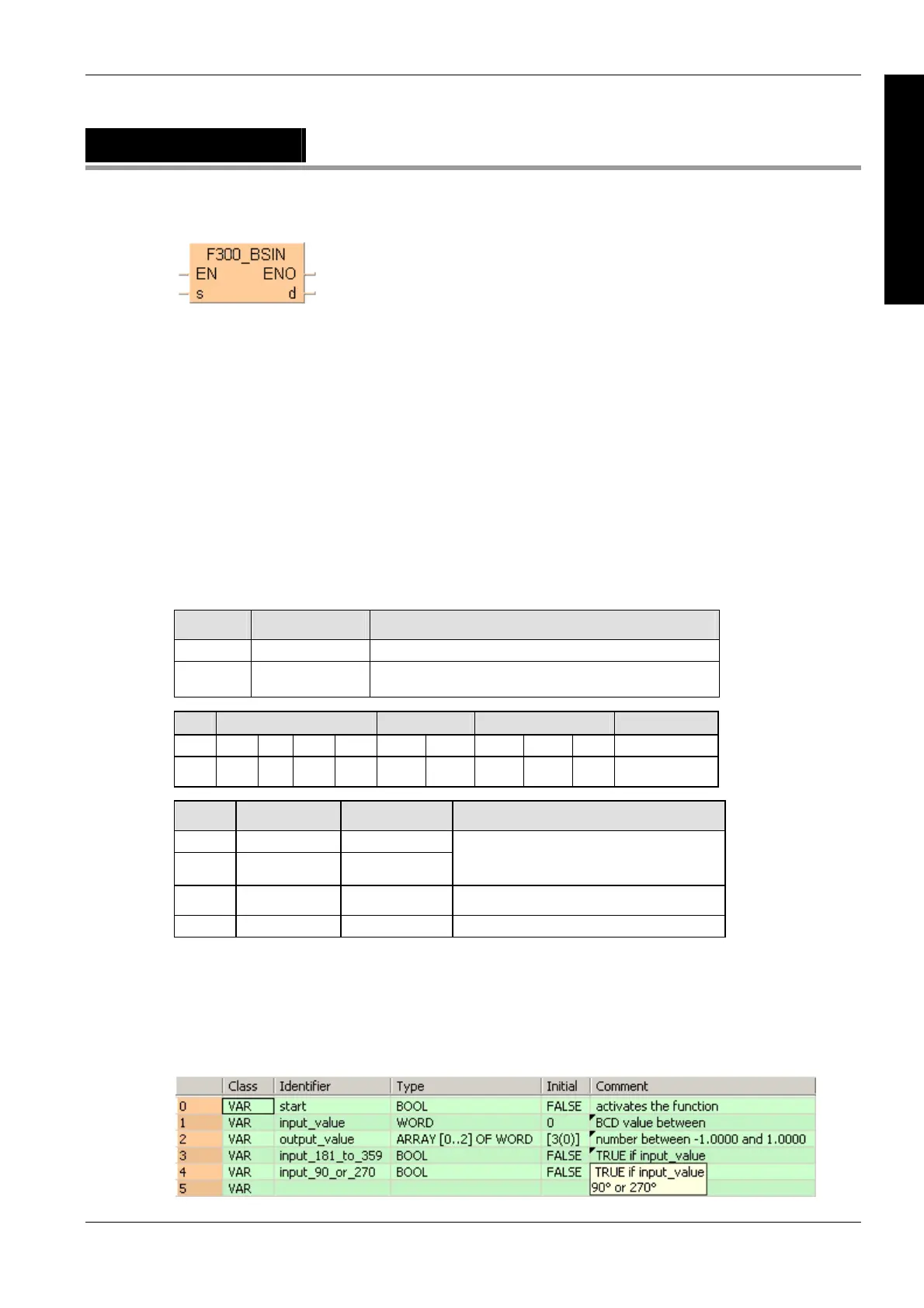
POU header
All input and output variables used for programming this function have been declared in the POU
header.

 Loading...


