High-speed counter instructions
891
Part III FP Instructions
28.2 Writing the high-speed counter control code
The special data register where the high-speed counter and pulse output control code are stored
can be accessed with the system variable sys_wHscOrPulseControlCode. (The system variable
sys_wHscOrPulseControlCode corresponds to special data register DT90052.)
Operations performed by the high-speed counter control code
Clearing high-speed counter instructions (bit 3)
Enabling/disabling the reset input (hardware reset) of the high-speed counter (bit
2)
Enabling/disabling counting operations (bit 1)
Resetting the elapsed value (software reset) of the high-speed counter to 0 (bit 0)
The control code settings for each channel can be monitored using the system variables
sys_wHscChannelxControlCode or sys_wPulseChannelxControlCode (where x=channel number).
The settings of this system variable remain unchanged until another setting operation is executed.
Description for FP, FP-X, FP0R:
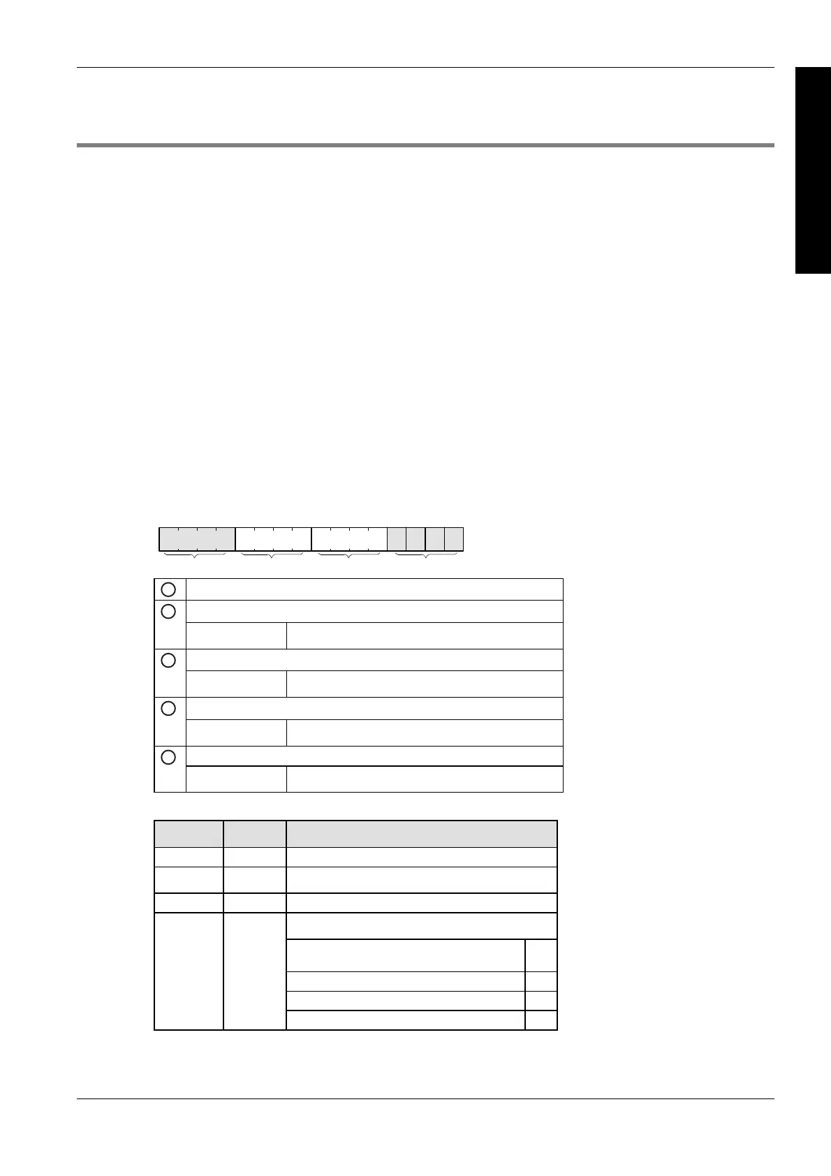
Bits 0–15 of the control code are allocated in groups of four. The bit setting in each group is
represented by a hex number (e.g. 0002 0000 0000 1001 = 16#2009).
15 12 11 8 7 4 3 0
IIIIIIIV
1
Channel number (channel n: 16#n)
Clear high-speed counter instruction (bit 3)
2
0: continue 1: clear
Reset input (bit 2) (see note)
3
0: enabled 1: disabled
Count (bit 1)
4
0: permit 1: prohibit
Reset elapsed value to 0 (bit 0)
5
0: no 1: yes
Example: 16#2009
Group Value Description
IV 2 Channel number: 2
III 0 (fixed)
II 0 (fixed)
Hex 9 corresponds to binary 1001
Clear high-speed counter instruction: clear
(bit 3)
1
Reset input: enabled (bit 2) 0
Count: permit (bit 1) 0
I 9
Reset elapsed value to 0: yes (bit 0) 1