Data transfer via communication ports
780
Part III FP Instructions
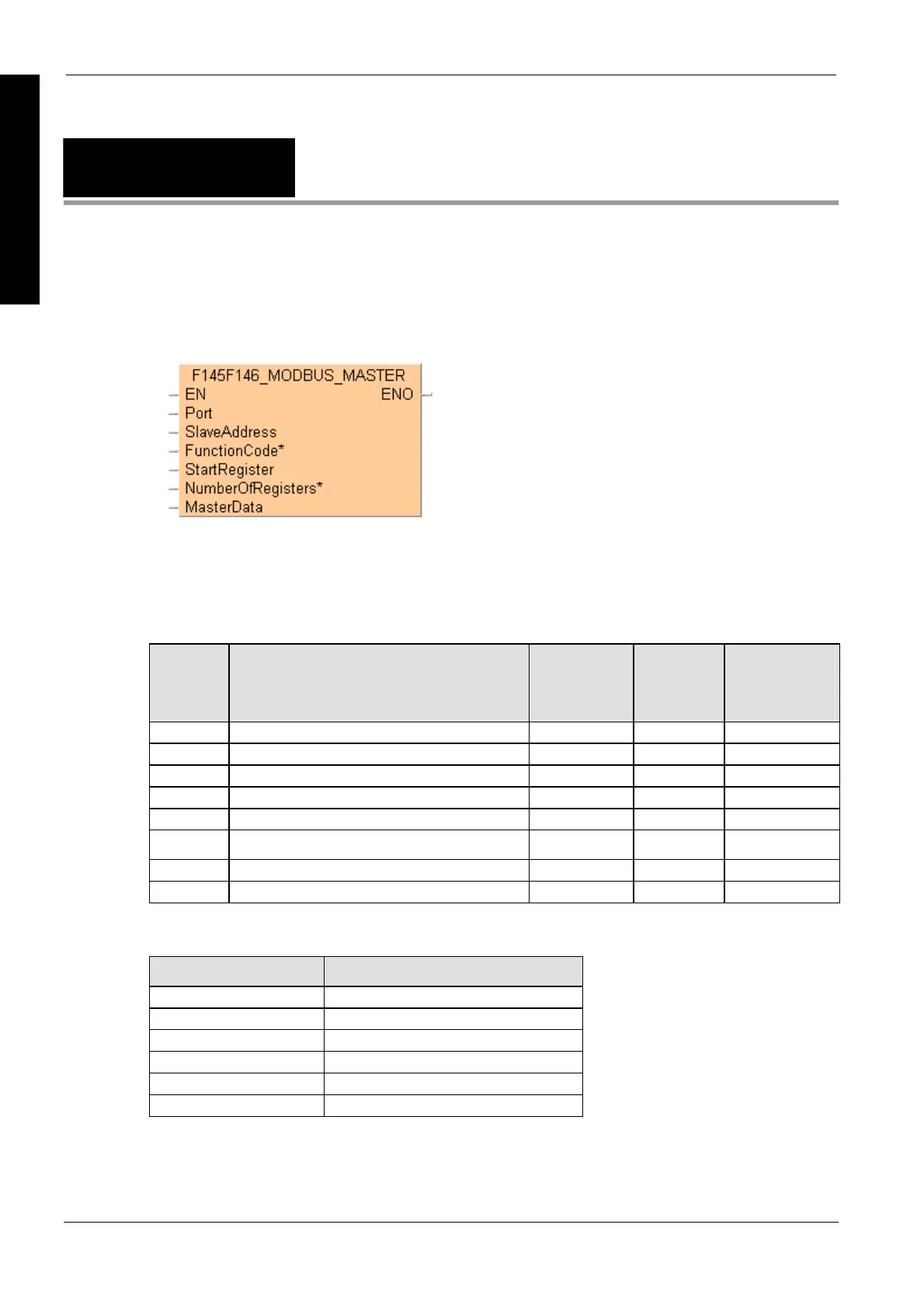
F145F146_MODBUS
_MASTER
Write data to slave or read data from slave
This instruction is identical to F145F146_MODBUS_COMMAND (see page 777), but it also
supports slave addresses higher than 99 and a wider range for the start register.
In contrast to other F145 or F146 instructions, the required Modbus command can directly be set
by the parameter FunctionCode*.
General programming information for F145 and F146 (see page 766)
Commands supported by
the master:
Function
code
System constant Start register Number of
registers
Reference
numbers
(depending on
Modbus slave)
01 SYS_MODBUS_01_READ_COIL 0–65535 1–2040 000001–065536
02 SYS_MODBUS_02_READ_INPUT 0–65535 1–2040 100001–165536
03 SYS_MODBUS_03_READ_HOLDING_REGISTER 0–65535 1–127 400001–465536
04 SYS_MODBUS_04_READ_INPUT_REGISTERS 0–65535 1–127 300001–365536
5 SYS_MODBUS_05_FORCE_COIL 0–65535 1 000001–065536
6 SYS_MODBUS_06_PRESET_REGISTER 0–65535 1 400001–465536
15 SYS_MODBUS_15_FORCE_COILS 0–65535 2–2040 000001–065536
16 SYS_MODBUS_16_PRESET_REGISTERS 0–65535 2–127 400001–465536
Modbus specifications for Panasonic PLCs:
Reference numbers Address area of Panasonic PLCs
From 000001 From Y0
From 002049 From R0
From 100001 From X0
From 400001 From DT0
From 300001 From WL0
From 302001 From LD0
For reference number and address area ranges supported by the Panasonic PLCs, please refer to the User's
Manual of the PLC. If the reference number is outside the supported range, an error is returned.
Description
Write data from a master to a slave or read data from a slave via the serial port (COM1 or COM2)
depending on the function code. The Modbus RTU protocol (see communication mode (see page
712)) must be set in the system registers (see page 1273). Select "Modbus RTU Master/Slave" for
the desi
red
port.

 Loading...


