Data transfer via communication ports
777
Part III FP Instructions
Example
In this example the function has been programmed in ladder diagram (LD) and structured text (ST).
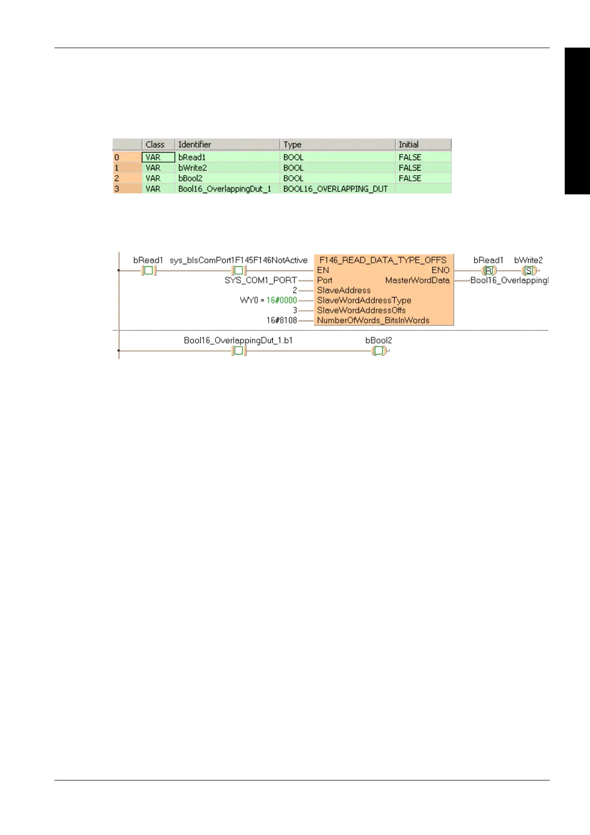
POU header
All input and output variables used for programming this function have been declared in the POU
header.
Body
If bRead1 and sys_bIsComPort1F145F146NotActive are set to TRUE, the output Y38 of slave 2
is read and written to bit 1 of Bool16_OverlappingDut_1.w0. This bit can be accessed by
Bool16_OverlappingDut_1.b1 and is copied to bBool2.
LD
ST
When programming with structured text, enter the following:
if (bRead1 and sys_bIsComPort1F145F146NotActive) then
F146_READ_DATA_TYPE_OFFS(Port := SYS_COM1_PORT,
SlaveAddress := 2,
SlaveWordAddressType := WY0,
SlaveWordAddressOffs := 3,
NumberOfWords_BitsInWords := 16#8108,
MasterWordData =>
Bool16_OverlappingDut_1.w0);
end_if;
bBool2 := Bool16_OverlappingDut_1.b1;

 Loading...


