Basics
31
1.2.2 IEC Addresses
The composition of an IEC-1131 address depends on:
operand type
data type
slot no. of the unit (word address)
relay no. (bit address)
PLC type
In- and Outputs are the most important components of a programmable logic controller (PLC). The PLC
receives signals from the input relays and processes them in the PLC program. The results can either be stored
or sent to the output relays, which means the PLC controls the outputs.
A PLC provides special memory areas, in short “M”, to store interim results, for example.
If you want to read the status of the input 1 of the first module and control the output 4 of the second module, for
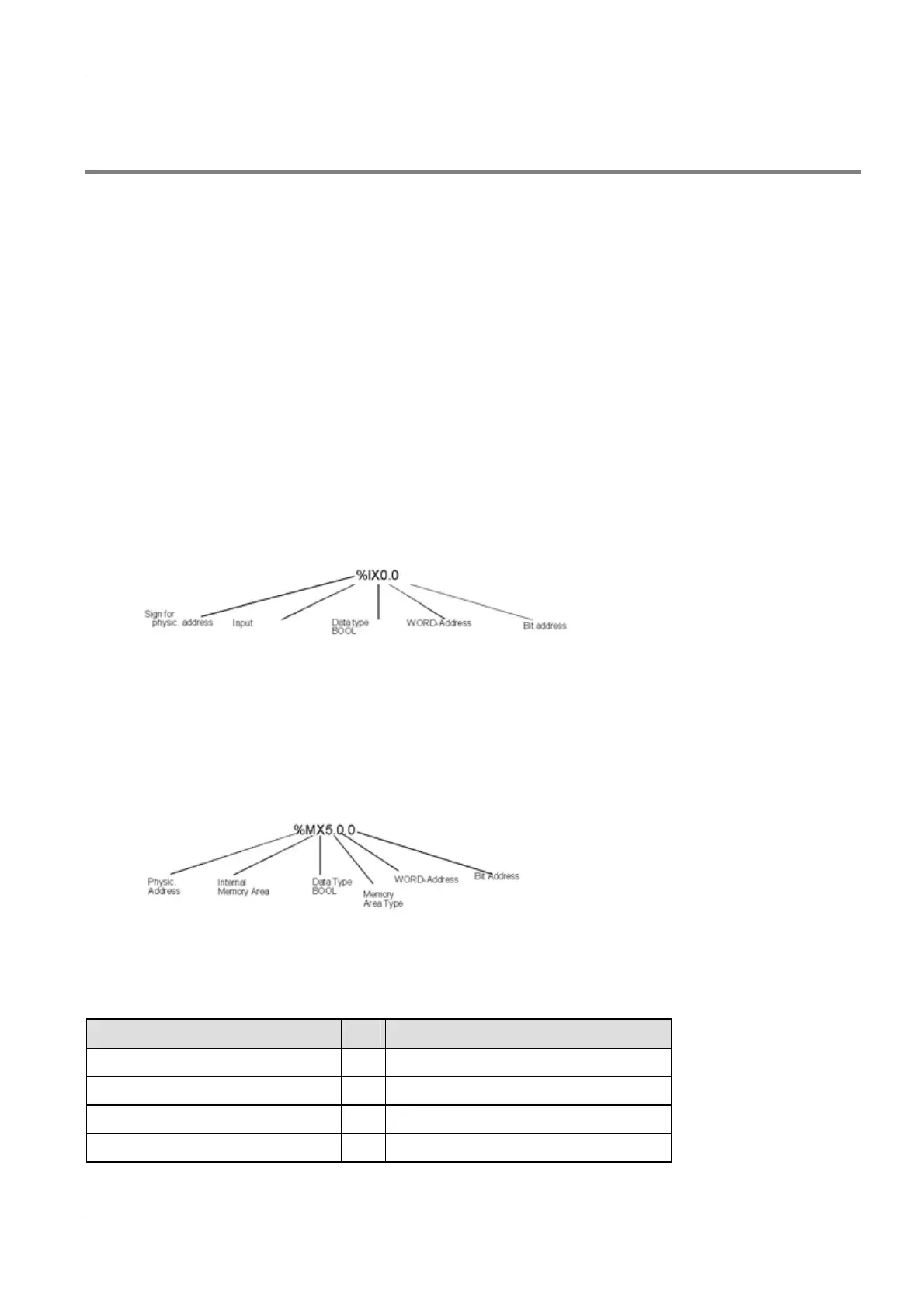
example, you need the physical address of each in-/output. Physical FPWIN Pro addresses are composed of
the per cent sign, an abbreviation for in-/output, an abbreviation for the data type and of the word and bit
address:
Example IEC address for an input
The per cent sign is the indicator of a physical address. “I” means input, “X” means data type BOOL.
The first zero represents the word address (slot no.) and the second one the bit address. Note that
counting starts with zero and that counting word and bit addresses differs among the PLC types.
Each PLC provides internal memory areas (M) to store interim results, for example. When using internal
memory areas such as data registers, do not forget the additional number (here 5) for the memory type:
Example IEC address for an internal memory area
Bit addresses do not have to be defined for data registers, counters, timers, or the set and actual
values.
According to IEC 1131, abbreviations for in- and output are “I” and “Q”, respectively. Abbreviations for the
memory areas are as follows:
Memory Type No. Example
Internal Relay (R)
0 %MX0.900.0 = internal relay R9000
Timer (T)
1 %MX1.200 = counter no. 200
Counter (C)
2 %MX2.100 = counter no. 100
Set Value counters/timers (SV)
3 %MW3.200 = set value of the counter no. 200

 Loading...


