Bitwise Boolean instructions
518
Part III FP Instructions
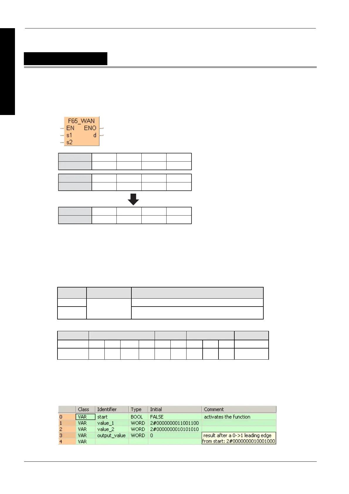
F65_WAN
16-bit data AND
·········
s1
15
010
12
0
11
110
8
1
7
101
4
1
3
100
0
1
·········
s2
15
000
12
0
11
000
8
0
7
111
4
1
3
111
0
1
·········
d
15
000
12
0
11
000
8
0
7
101
4
1
3
100
0
1
Bit position
Bit position
Bit position
start: ON
This instruction also exists as a P instruction (for FP2/2SH, FP3/5, FP10/10SH PLC types), which
is only executed at the rising edge of the EN trigger. Select [Insert P instruction] from the
"Instructions" pane if you require a P instruction. To facilitate reuse, the instruction then appears
under "Recently used" in the pop-up menu. Press <Ctrl>+<Shift>+<v> within the programming
area to open the list of recently used elements.
PLC types
Availability of F65_WAN (see page 1326)
Variable Data type Function
s1, s2 16-bit area or 16-bit equivalent constant to be compared
d
ANY16
16-bit area for storing AND operation result
The variables s1, s2 and d have to be of the same data type.
For Relay T/C Register Constant
s1, s2 WX WY WR WL SV EV DT LD FL dec. or hex.
d - WY WR WL SV EV DT LD FL -
Description
Executes AND operation of each bit in 16-bit equivalent constant or 16-bit data specified by s1 and
s2 if the trigger EN is in the ON-state. The AND operation result is stored in the 16-bit area
specified by d. When 16-bit equivalent constant is specified by s1 or s2, the AND operation is
performed internally converting it to 16-bit binary expression. You can use this instruction to turn
OFF certain bits of the 16-bit data.
Data types
Operands
Example
In this example the function has been programmed in ladder diagram (LD) and structured text
(ST).The same POU header is used for all programming languages.
POU header
All input and output variables used for programming this function have been declared in the POU
header.

 Loading...


