Appendix Programming Information
1257
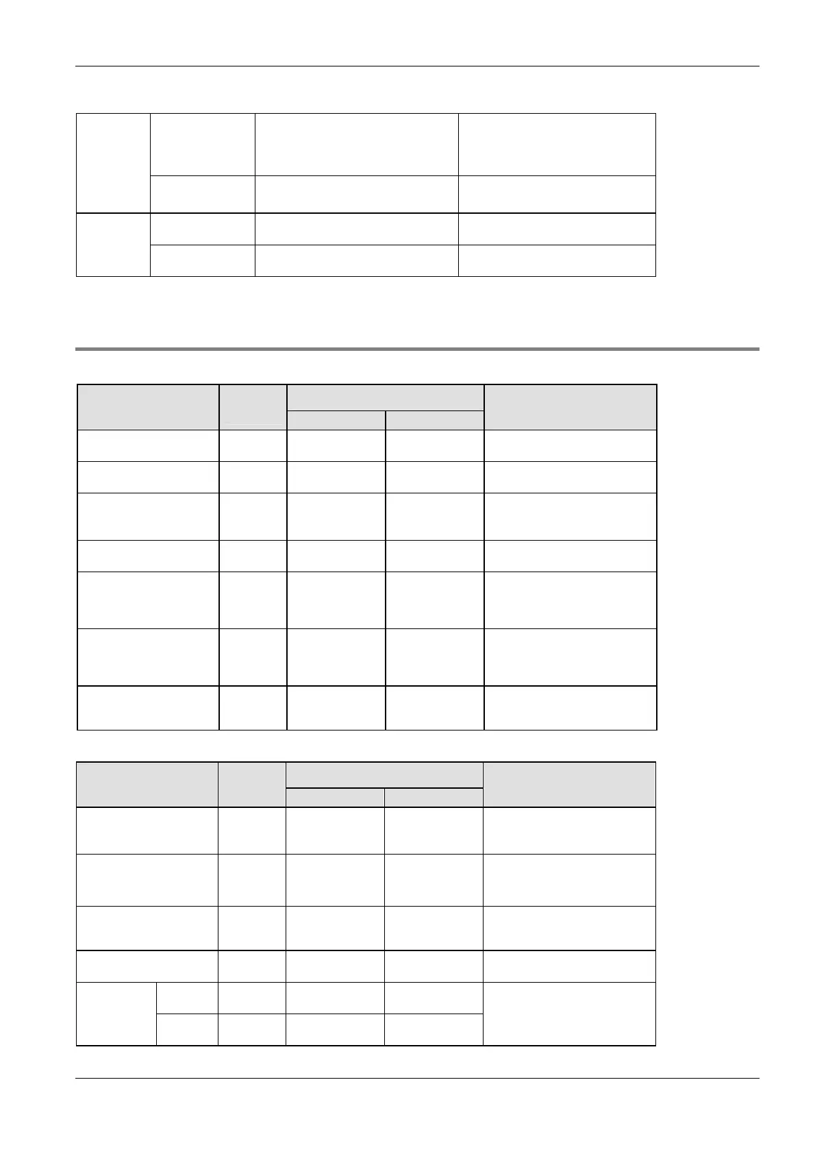
Non-hold type 976 points
(R0–R60F)
61 words
(WR0–WR60)
880 points
(R0–R54F)
55 words
(WR0–WR54)
Internal
relays
Hold type 32 points (R610–R62F)
2 words (WR61–WR62)
128 points (R550–R62F)
8 words (WR55–WR62)
Non-hold type 1652 words
(DT0–DT1651)
6112 words
(DT0–DT6111)
Data
registers
Hold type 8 words
(DT1652–DT1659)
32 words (DT6112–DT6143)
40.7.2 Relays and memory areas for FP0R
Relays [bits]
Available address area Type Memory
size
FP IEC
Function
External input relays
1)
1760 X0–X109F %IX0.0–
%IX109.15
Turn on or off based on external
input.
External output relays
1)
1760 Y0–Y109F %QX0.0–
%QX109.15
Turn on or off external outputs
based on the operation result.
Internal relays
2)
4096 R0–R255F %MX0.0.0–
%MX0.255.15
Used internally by the PLC
program to store bit information.
Link relays
2)
2048 L0–L127F %MX7.0.0–
%MX7.127.15
Shared by multiple PLCs
connected using PLC link.
Timer relays
2)
3)
1024 T0–T1007/
C1008-C1023
%MX1.0–
%MX1.1007/
%MX2.1008–
%MX2.1023
Turn on when the value set with
a TM instruction for the timer with
the same number has reached 0.
Counter relays
2)
3)
1024 C1008–C1023/
T0–T1007
%MX2.1008–
%MX2.1023/
%MX1.0–
%MX1.1007
Turn on when the value set with
a CT instruction for the counter
with the same number has
reached 0.
Special internal relays 224 R9000–R913F %MX0.900.0–
%MX0.913.15
Turn on or off based on specific
conditions. Used internally as a
flag.
Memory area [words]
Available address area Type Memory
size
FP IEC
Function
External input relays
1)
110 WX0–WX109 %IW0–
%IW109
Code for specifying 16 external
input points as one word (16 bits)
of data.
External output relays
1)
110 WY0–WY109 %QW0–
%QW109
Code for specifying 16 external
output points as one word (16
bits) of data.
Internal relays
2)
256 WR0–WR255 %MW0.0–
%MW0.255
Code for specifying 16 internal
relays as one word (16 bits) of
data.
Link relays 128 WL0–WL127 %MW7.0–
%MW7.127
Code for specifying 16 link relays
as one word (16 bits) of data.
C10,
C14, C16
12315 DT0–DT12312 %MW5.0–
%MW5.12312
Data
registers
2)
C32, T32,
F32
32763 DT0–DT32762 %MW5.0–
%MW5.32762
Data memory used in a program.
Data is handled in 16-bit units
(one word).

 Loading...


