Conversion instructions
660
Part III FP Instructions
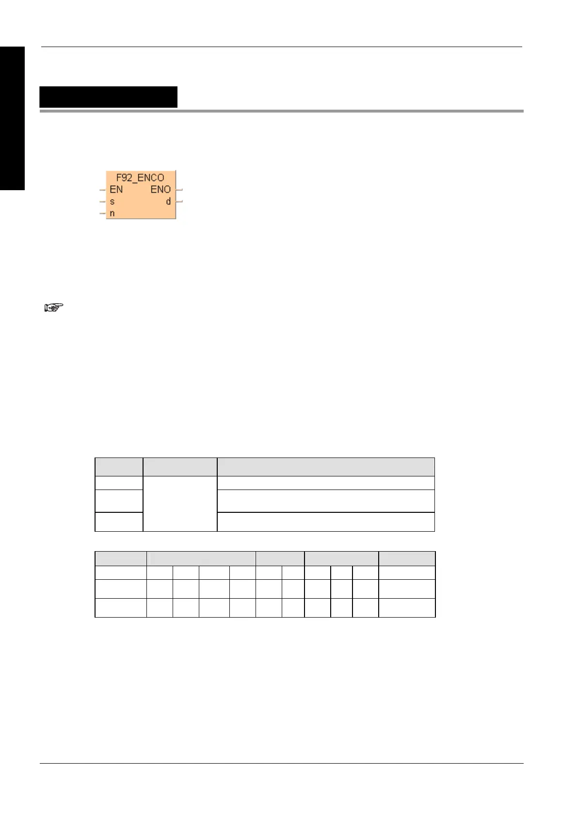
F92_ENCO
Encode bit state -> hexadecimal
b specifies the starting bit position of destination data d and the number of bits to be encoded using
hexadecimal data:
Bit No. 0 to 3 number of bits to be encoded
Bit No. 8 to 11 starting bit position of destination data to be encoded
(The bits No. 4 through No. 7 and No. 12 through No. 15 are invalid.)
Put at least one bit into the area to be checked to avoid an error message
from the PLC.
When several bits are set, the uppermost bit is evaluated.
This instruction also exists as a P instruction (for FP2/2SH, FP3/5, FP10/10SH PLC types), which
is only executed at the rising edge of the EN trigger. Select [Insert P instruction] from the
"Instructions" pane if you require a P instruction. To facilitate reuse, the instruction then appears
under "Recently used" in the pop-up menu. Press <Ctrl>+<Shift>+<v> within the programming
area to open the list of recently used elements.
PLC types
Availability of F92_ENCO (see page 1326)
Variable Data type Function
s starting 16-bit area to be encoded (source)
n control data to specify the starting bit position and number of
bits to be encoded
d
ANY16
16-bit area for storing encoded data (destination)
The variables s, n and d have to be of the same data type.
For Relay T/C Register Constant
s WX WY WR WL SV EV DT LD FL -
n WX WY WR WL SV EV DT LD FL dec. or hex.
d - WY WR WL SV EV DT LD FL -
Description
Encodes the contents of data specified by s according to the contents of n if the trigger EN is in the
ON-state. The encoded result is stored in the 16-bit area specified by d starting with the specified
bit position. Invalid bits in the area specified for the encoded result are set to 0.
Data types
Operands

 Loading...


