Appendix Programming Information
1268
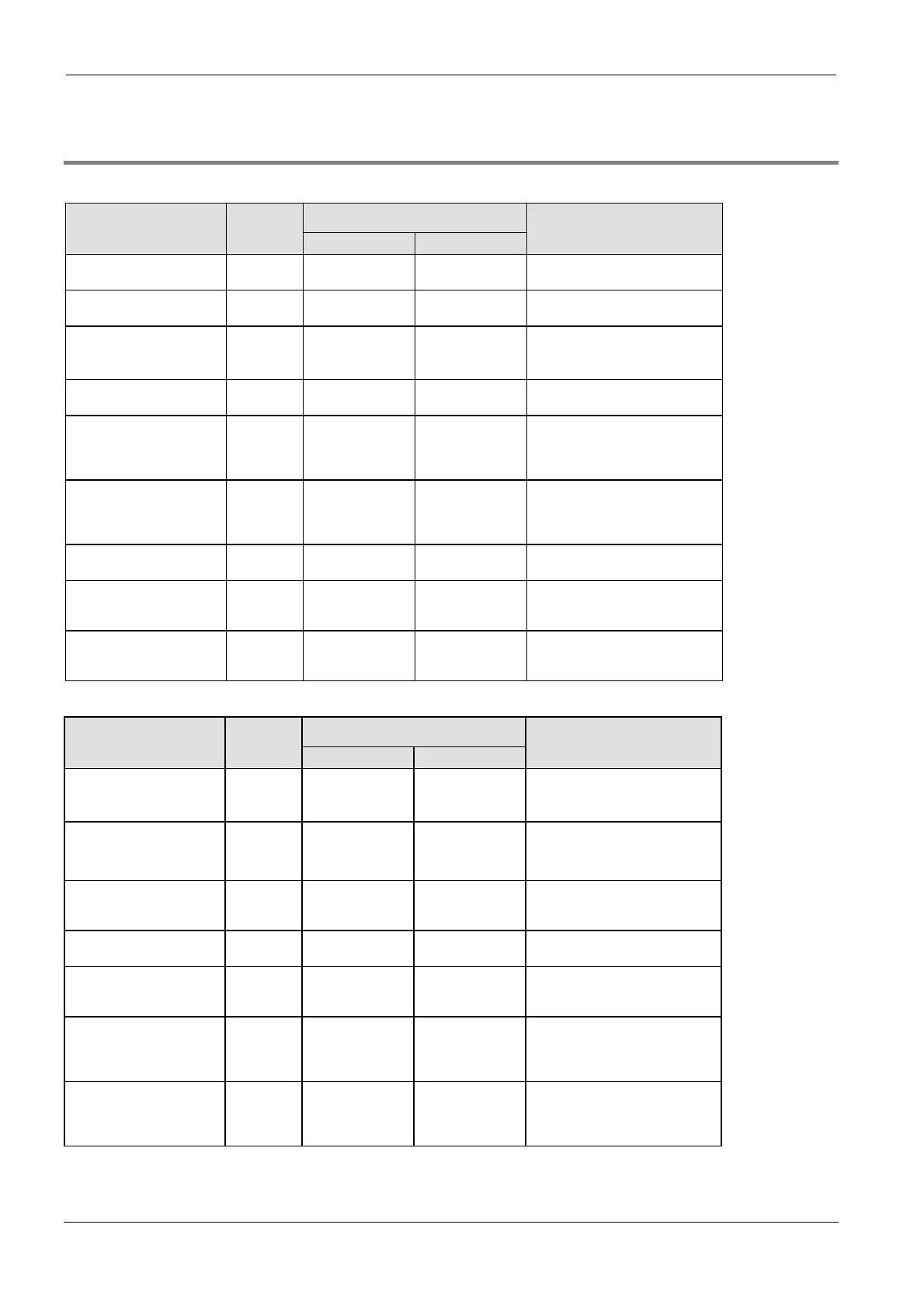
40.7.7 Relays and memory areas for FP2SH
Relays [bits]
Available address area Type Memory
size
F/P IEC
Function
External input relays 8192 X0–X511F %IX0.0–
%IX511.15
Turn on or off based on external
input.
External output relays 8192 Y0–Y511F %QX0.0–
%QX511.15
Turn on or off external outputs
based on the operation result.
Internal relays
1)
14192 R0–R886F %MX0.0.0–
%MX0.886.15
Used internally by the PLC
program to store bit information.
Link relays
1)
10240 L0–L639F %MX7.0.0–
%MX7.639.15
Shared by multiple PLCs
connected using PLC link.
Timer relays
1)
2)
3072 T0–T2999/
C3000–C3071
%MX1.0–
%MX1.2999/
%MX2.3000–
%MX2.3071
Turn on when the value set with
a TM instruction for the timer with
the same number has reached 0.
Counter relays
1)
2)
3072 C3000–C3071/
T0–T2999
%MX2.3000–
%MX2.3071/
%MX1.0–
%MX1.2999
Turn on when the value set with
a CT instruction for the counter
with the same number has
reached 0.
Pulse relays 2048 P0–P127F %MX11.0.0–
%MX11.127.15
Turn on for one scan only. Used
internally by the PLC program.
Error alarm relays 2048 E0–E127F %MX10.0.0–
%MX10.127.15
Turns on in the event of error.
The error history is stored in
dedicated data registers.
Special internal relays 176 R9000–R910F %MX0.900.0–
%MX0.910.15
Turn on or off based on specific
conditions. Used internally as a
flag.
Memory area [words]
Available address area Type Memory
size
F/P IEC
Function
External input relays 512 WX0–WX127 %IW0–
%IW127
Code for specifying 16 external
input points as one word (16 bits)
of data.
External output relays 512 WY0–WY127 %QW0–
%QW127
Code for specifying 16 external
output points as one word (16
bits) of data.
Internal relays 887 WR0–WR252 %MW0.0–
%MW0.252
Code for specifying 16 internal
relays as one word (16 bits) of
data.
Link relays 640 WL0–WL127 %MW7.0–
%MW7.127
Code for specifying 16 link relays
as one word (16 bits) of data.
Data registers
1)
10240 DT0–DT5999 %MW5.0–
%MW5.5999
Data memory used in a program.
Data is handled in 16-bit units
(one word).
Link registers
1)
8448 LD0–LD255 %MW8.0–
%MW8.255
Data memory shared by multiple
PLCs connected using PLC link.
Data is handled in 16-bit units
(one word)..
Timer/counter set value
area
1)
3072 SV0–SV1023 %MW3.0–
%MW3.1023
Data memory for storing the set
values of timers or counters. The
values are stored by
timer/counter number.

 Loading...


