Appendix Programming Information
1267
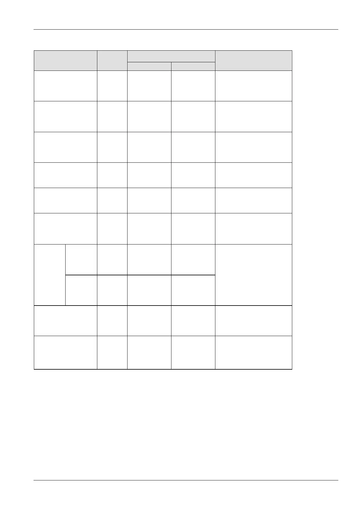
Available address area Type Memory
size
F/P IEC
Function
Internal relays
2)
126 DWR0–DWR254 %MD0.0–
%MD0.254
Code for specifying 32 internal
relay points as a double word (32
bits) of data.
Link relays 64 DWL0–DWL126 %MD7.0–
%MD7.126
Code for specifying 32 link relay
points as a double word (32 bits)
of data.
Data registers
2)
3000 DDT0–
DDT32763
%MD5.0–
%MD5.32763
Data memory used in a program.
Data is handled in 32-bit units
(double word).
Link registers
2)
128 DLD0–DLD254 %MD8.0–
%MD8.254
Data memory shared by multiple
PLCs connected using PLC link.
Data is handled in 32-bit units
(double word).
Timer/counter set value
area
2)
512 DSV0–DSV1022 %MD3.0–
%MD3.1022
Data memory for storing the set
values of timers or counters. The
values are stored by
timer/counter number.
Timer/counter elapsed
value area
2)
512 DEV0–DEV1022 %MD4.0–
%MD4.1022
Data memory for storing the
elapsed values during operation
of timers or counters. The values
are stored by timer/counter
number.
12k type 7166 DFL0–DFL14331 %MD9.0–
%MD9.14331
File
registers
1)
3)
32k type
(expanded)
15358 DFL0–DFL30715 %MD9.0–
%MD9.30715
Data memory used in a program.
Data is handled in 16-bit units
(one word).
Special data registers 128 DDT90000–
DDT90254
%MD5.90000–
%MD5.90254
Data memory for storing settings
and error codes.
Index registers 7 DI0–DID %MD6.0–
%MD6.13
Data memory used to modify
constants and memory area
addresses.
1)
There are two memory types, the hold type that saves the conditions that exist just before turning the power
off or changing from RUN to PROG mode, and the non−hold type that resets them. The hold and non−hold
type memory areas can be changed by setting the system registers.
2)
The number of points for timer and counter relays can be changed using system register 5. The numbers in
the table are the default settings.
3)
The size of the file registers varies depending on the settings of system registers 0, 1, and 2.

 Loading...


