Basics
32
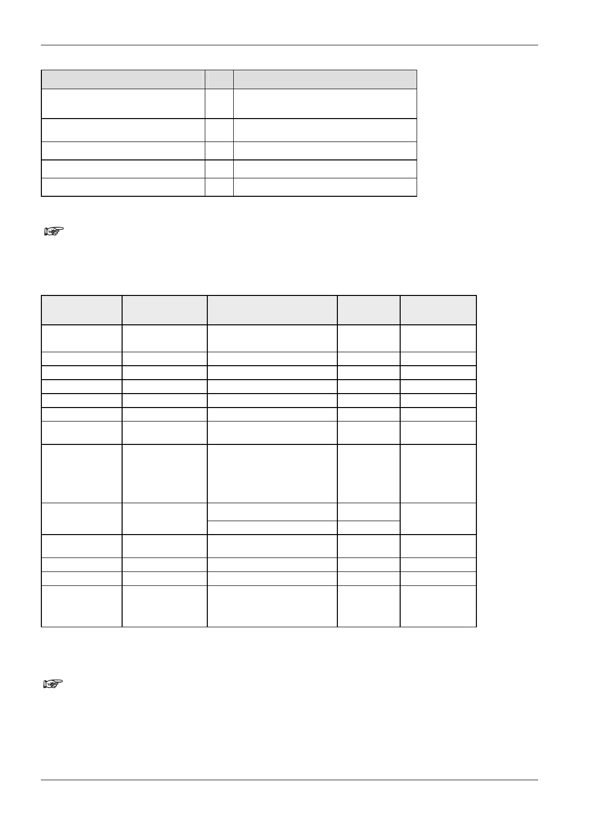
Memory Type No. Example
Elapsed Value counters/timers
(EV)
4 %MW4.100 = elapsed value of the timer no. 100
Data Registers (DT, DDT)
5 %MW5.9001 = data register DT9001
%MD5.90001 = 32-bit data register DDT90001
Link Relay (WL)
7 %MW7.63 = link relay 63
Link Register (LD)
8 %MW8.127 = link register 127
File Register (FL)
9 %MW9.800 = file register 800
Tables with hardware addresses can be found in the hardware
description of your PLC.
The following data types are available:
Keyword Data type Range Reserved
memory
Initial value
BOOL Boolean 0 (FALSE)
1 (TRUE)
1 bit 0
WORD Bit string of length 16 0–65535 16 bits 0
DWORD Bit string of length 32 0–4294967295 32 bits 0
INT Integer -32768–32,767 16 bits 0
DINT Double integer -2147483648– 2147483647 32 bits 0
UINT Unsigned integer 0–65,535 16 bits 0
UDINT Unsigned double
integer
0–4294967295 32 bits 0
REAL Real number -3.402823466*E38–
-1.175494351*E-38
0.0
+1.175494351*E-38–
+3.402823466*E38
32 bits 0.0
T#0s–T#327.67s 16 bits
1)
TIME Duration
T#0s–T#21474836.47s 32 bits
1)
T#0s
DATE_AND_TIME Date and time DT#2001-01-01-00:00:00–
DT#2099-12-31-23:59:59
32 bits DT#2001-01-01-00
:00:00
DATE Date D#2001-01-01–D#2099-12-31 32 bits D#2001-01-01
TIME_OF_DAY Time of day TOD#00:00:00–TOD#23:59:59 32 bits TOD#00:00:00
STRING Variable-length
character string
1–32767 bytes (ASCII) depending
on PLC memory size
2 words for the
head + (n+1)/2
words for the
characters
''
1)
Depending on PLC type
Please take into account that not all data types can be used with each
IEC command.
Numbering of in-/output addresses depends on the type of PLC used (see respective hardware description). For
FP0, FP-Sigma the addresses are not serially numbered. Counting restarts with zero at the first output.
Supposing you have one FP1-C24 with 16 inputs and 8 outputs, the resulting addresses are: for the input:
%IX0.0 - %IX0.15, and for the output: %QX0.0 - %QX0.7. In other words the counting for the word and bit

 Loading...


