High-speed counter instructions
892
Part III FP Instructions
Description for FP0, FP-e:
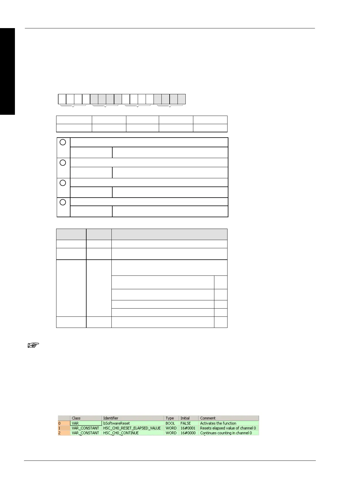
Bits 0–15 of the control code are allocated in groups of four, each group containing the settings for
one channel. The bit setting in each group is represented by a hex number (e.g. 0000 0000 1001
0000 = 16#90).
15 12 11 8 7 4 3 0
IIIIIIIV
Group IV III II I
Channel 3 2 1 0
Clear high-speed counter instruction (bit 3)
1
0: continue 1: clear
Reset input (bit 2) (see note)
2
0: enabled 1: disabled
Count (bit 1)
3
0: permit 1: prohibit
Reset elapsed value to 0 (bit 0)
4
0: no 1: yes
Example: 16#90
Group Value Description
IV 0 –
III 0 –
Channel number: 1
Hex 9 corresponds to binary 1001
Clear high-speed counter instruction: clear (bit
3)
1
Reset input: enabled (bit 2) 0
Count: permit (bit 1) 0
II 9
Reset elapsed value to 0: yes (bit 0) 1
I 0 –
Turning the reset input to TRUE, sets the elapsed value to 0. Use the reset input
setting (bit 2) to disable the reset input allocated in the system registers.
Software reset for channel 0
Example 1
The first example shows how to perform a software reset for channel 0, and the second example
shows how to perform a software reset for channel 1.
POU header
All input and output variables used for programming this function have been declared in the POU
header.

 Loading...


