Pulse output instructions
1022
Part III FP Instructions
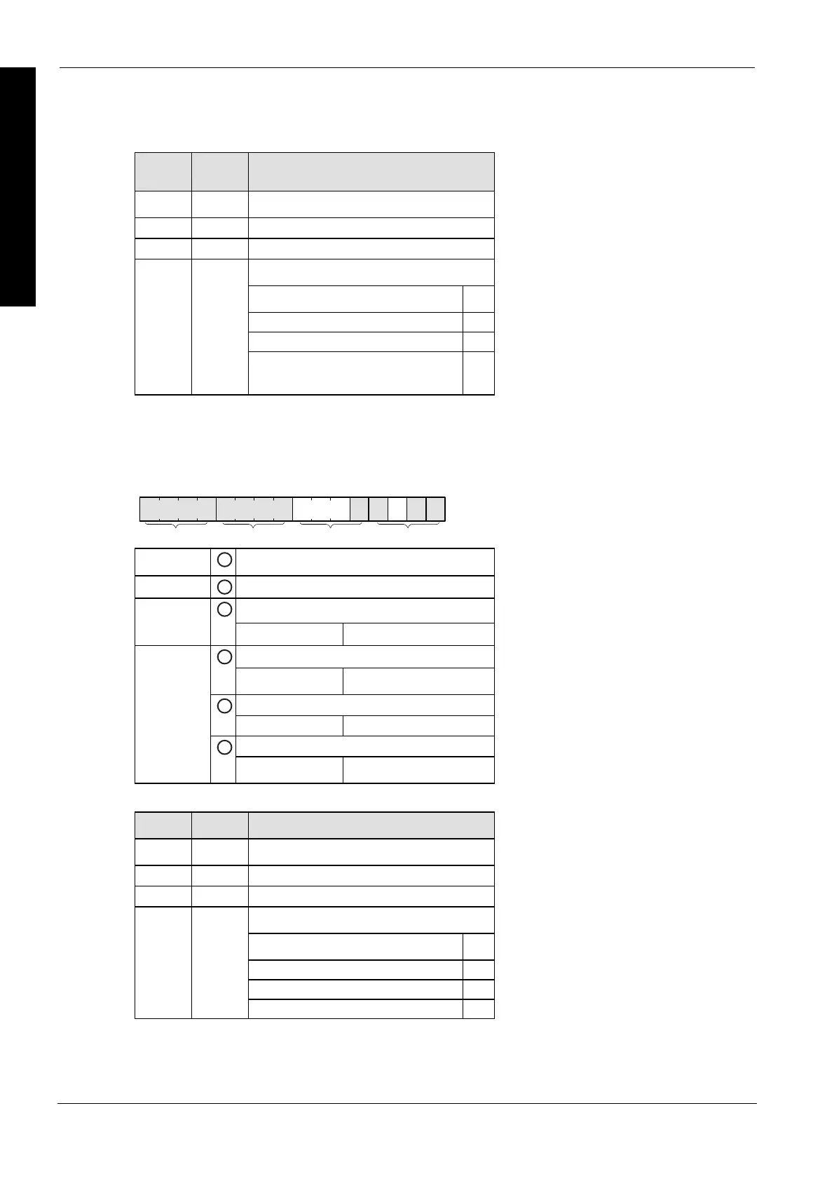
Example: 16#2009
Group Value Description
IV
2 Channel number: 2
III
0 (fixed)
II
0 Near home input: FALSE
Hex 9 corresponds to binary 1001
Pulse output: stop (bit 3) 1
(bit 2, fixed) 0
Count: permit (bit 1) 0
I
9
Reset elapsed value to 0: yes (bit 0) 1
Description for FP-X:
Bits 0–15 of the control code are allocated in groups of four. The bit setting in each group is
represented by a hex number (e.g. 0002 0001 0000 1001 = 16#2109).
15 12 11 8 7 4 3 0
IIIIIIIV
Group IV
1
Channel number (channel n: 16#n)
Group III
2
1 (fixed)
Near home input (bit 4) (see note)
Group II
3
0: FALSE 1: TRUE
Pulse output (bit 3)
4
0: continue 1: stop
Count (bit 1)
5
0: permit 1: prohibit
Reset elapsed value to 0 (bit 0)
Group I
6
0: no 1: yes
Example: 16#2109
Group Value Description
IV
2 Channel number: 2
III
1 (fixed)
II
0 Near home input: FALSE
Hex 9 corresponds to binary 1001
Pulse output: stop (bit 3) 1
(Bit 2 fixed) 0
Count: permit (bit 1) 0
I
9
Reset elapsed value to 0: yes (bit 0) 1
Description for FP0R:
Bits 0–15 of the control code are allocated in groups of four. The bit setting in each group is

 Loading...


