EasyManuals Logo

Panasonic FP Series User Manual

Panasonic FP Series
1345 pages
To Next Page IconTo Next Page
To Previous Page IconTo Previous Page
Page #994 background imageLoading...
Page #994 background image
System register instructions
993
Part III FP Instructions
No. IEC address Set If
R9007
R9008
%MX0.900.7
%MX0.900.8
permanently
for an instant
any character other than a keyword is
specified
no comma is between the first and second
keywords
small letters of the alphabet are used to
specify the keyword
no communication cassette has been
installed when COM1 or COM2 has been
set
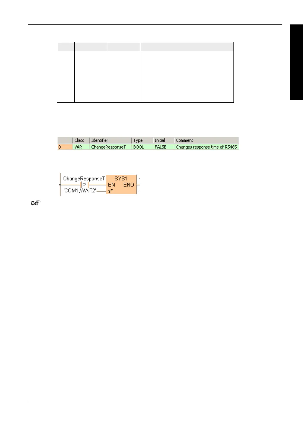
In this example the function SYS1 is programmed in ladder diagram (LD).
The values entered at s* will be right aligned automatically by the compiler.
Error flags
Example
POU header
The same POU header is used for all programming languages.
Body
When ChangeResponseT turns on, the response time for COM port 1 is delayed by 2s.
LD

Table of Contents

Other manuals for Panasonic FP Series

Questions and Answers:

Question and Answer IconNeed help?

Do you have a question about the Panasonic FP Series and is the answer not in the manual?

Panasonic FP Series Specifications

General IconGeneral
MountingDIN rail
TypePLC
Communication InterfaceRS-232, RS-485, Ethernet (depending on model)
Input Voltage100-240V AC or 24V DC (depending on model)
Output TypeRelay, Transistor
I/O PointsVaries by model
Operating Temperature0°C to 55°C
DimensionsVaries by model
WeightVaries by model

Related product manuals