System register instructions
992
Part III FP Instructions
Commercial
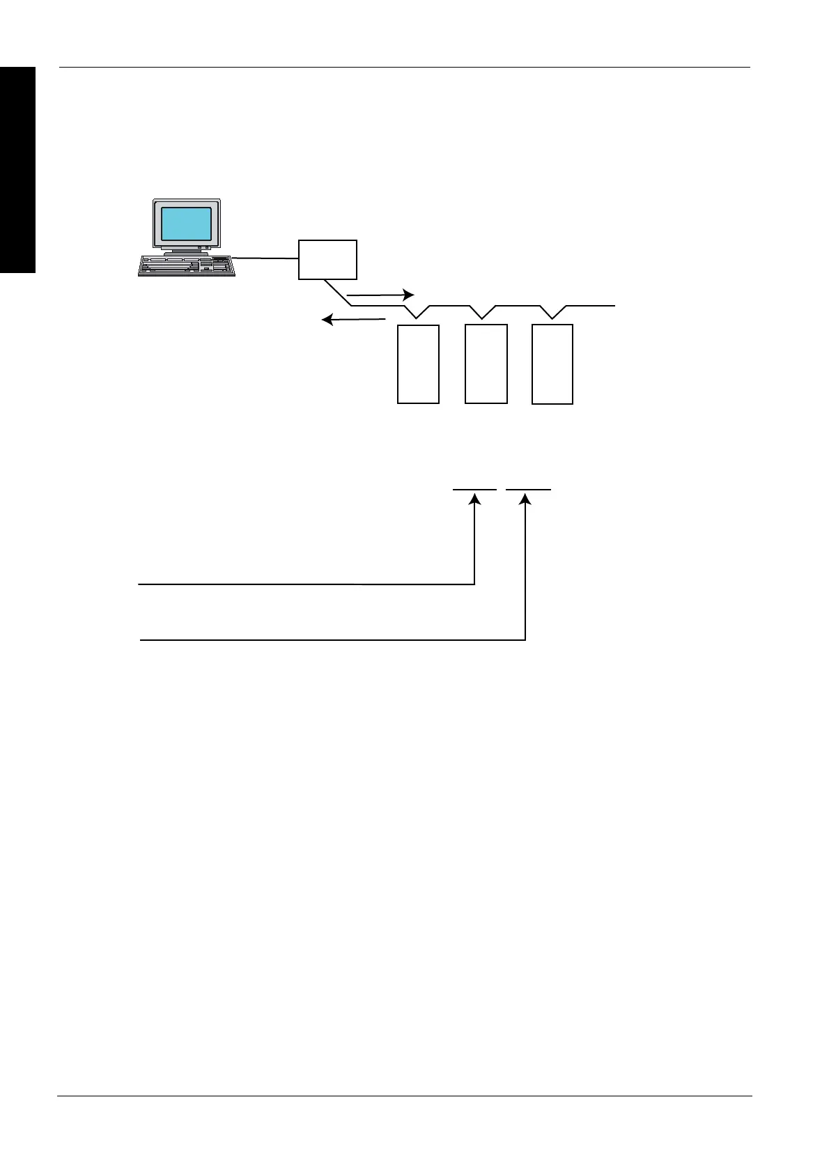
RS232C/RS485 converter
Response
External
device (PC)
Command
FP
Σ
FP
Σ
FP
Σ
Keyword setting
TOOL,
WAITn
Port used
Response time
TOOL: Tool port
WAIT0 to WAIT999: (n: 0 to 999)
COM2: COM 2 port
COM1: COM 1 port
If the communication mode has been set to the computer link mode, the set time is the scan time x
n (n: 0 to 999).
If the communication mode has been set to the PLC link mode, the set time is n s (n: 0 to 999).
If n = 0, the delay time set by this instruction will be set to "None".
Precautions during programming
This instruction is valid only if the setting on the controller side has been set to
the computer link mode or the PLC link mode. It is invalid in the general
communication mode.
Executing this instruction does not change the settings in the system registers.
We recommend using differential execution with this instruction.
When the power supply to the PLC is off, the settings set by this instruction are
cleared. (The set value will become 0.) If the mode is switched to the PROG.
mode after the instruction has been executed, however, the settings will be
retained.
If a commercial RS232C/RS485 converter is being used in the PLC link mode,
this instruction should be programmed in all of the stations (PLCs) connected to
the link.
Separate first and second keywords with a comma "," and do not use spaces.
Usage
Example
When a commercial RS232C/RS485 converter is being used to carry out communication between
a personal computer and the FP-, this instruction is used to return the PLC response after
switching of the enable signal has been completed on the converter side.

 Loading...


