Analog unit instructions
1125
Part IV Tool Instructions
Example
In this example the function has been programmed in ladder diagram (LD) and structured text
(ST).The same POU header is used for all programming languages.
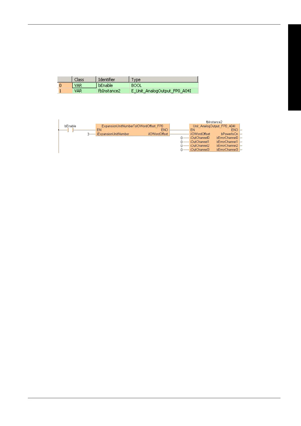
POU header
All input and output variables used for programming this function have been declared in the POU
header.
Body
If bEnable is set to TRUE, the function block converts the digital data (0–4000) of the analog unit
FP0-A04I with current output into analog data at the corresponding output channels (4–20mA).
LD
ST
IF bEnable THEN
fbInstance2(iIOWordOffset := iIOOffsetFP0,
iOutChannel0 := iOut1,
iOutChannel1 := iOut2,
iOutChannel2 := iOut3,
iOutChannel3 := iOut4,
bPowerIsOn => bOutPower2,
bErrorChannel0 => bOutError1,
bErrorChannel1 => bOutError2,
bErrorChannel2 => bOutError3,
bErrorChannel3 => bOutError4);
END_IF;

 Loading...


