Analog unit instructions
1124
Part IV Tool Instructions
The COM contacts are connected internally.
The COM contacts are connected internally.
Keep a distance of more than 100mm between the output line and the power
line/high-voltage line.
For wiring the analog outputs shielded twisted pair cables are recommended. Connect
the shield with the frame ground of the analog unit.
For wiring the analog outputs shielded twisted pair cables are recommended. Connect
the shield with the frame ground of the analog unit.
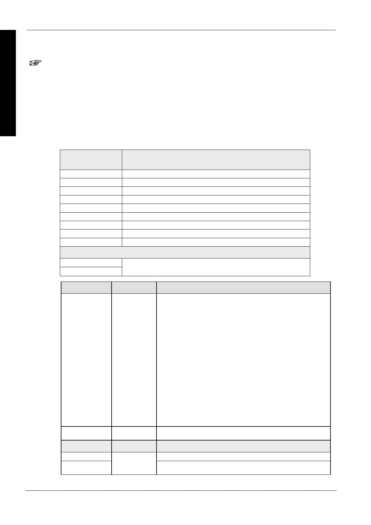
D/A conversion values
digital input value
range: 0–4000
current output (mA)
range: 4–20 mA
0 4.0
500 6.0
1000 8.0
1500 10.0
2000 12.0
2500 14.5
3000 16.0
3500 18.5
4000 20.0
values outside of range
-1
+4001
constant, the converted value exactly is based on the latest valid input value
Input variable Data type Function
iIOWordOffset
INT
The offset of the first WX/WY address of the RTD unit according to its
position.
FP0R, FP0, FP-Sigma: (use ExpansionUnitToIOWordOffset_FP0 (see
page 1128)) or
unit 1 => address 2, unit 2 => address 4, unit 3 => address 6
FP-X: (use Expa
nsionUnotToIOWordOffset_FPX_FP0 (see page 1129)) or
FP0 adapter address of
unit 1
address of
unit 2
address of
unit 3
1st unit 30 32 34
2nd unit 40 42 44
3rd unit 50 52 54
4th unit 60 62 64
5th unit 70 72 72
6th unit 80 82 84
7th unit 90 92 94
8th unit 100 102 104
iOutChannel0–
iOutChannel3
INT
0–4000 -> 4mA–20mA on the corresponding channel
Output variable Data type Function
bPowerIsOn Status data of unit (1: ON, 0: OFF)
bErrorChannel0–b
ErrorChannel3
BOOL
Status data channel (1: error, 0: normal)
Data types

 Loading...


