Basics
35
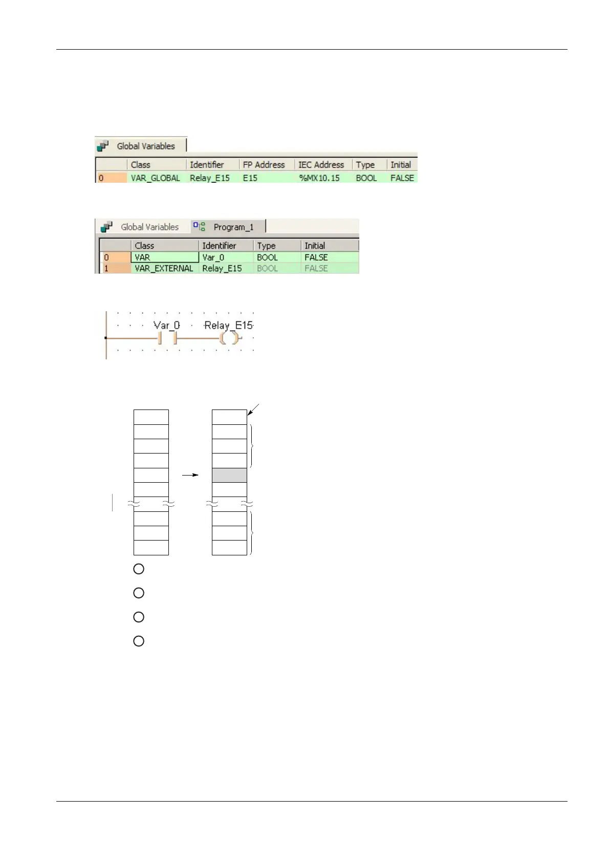
The diagram below illustrates the internal structure and address assignment in the special data register area of
this error buffer.
GVL
POU Header
LD
Error alarm diagram
DT90420
3
21
12
5
0
0
4
21
12
5
15
0
DT90421
DT90422
DT90400
DT90401
DT90402
DT90403
DT90404
DT90405
1
2
4
3
1
DT90400 Number of alarms that have occurred
2
DT90401–DT90419 Error alarm relays stored in the order they were set to TRUE
3
Error alarm E15 is set to TRUE
4
Time at which the first error alarm relay was set to TRUE:
DT90420 Second and minute data
DT90421 Hour and day data
DT90422 Month and year data
R9040 TRUE when one of the error alarm relays E0–E2047 is TRUE
Because in Control FPWIN Pro all write operations on error relays are internally compiled into SET (see page
508) and RST (see page 508) instructions, all write operations to an error relay affect the special internal relay

 Loading...


