EasyManuals Logo

Panasonic FP Series User Manual

Panasonic FP Series
1345 pages
To Next Page IconTo Next Page
To Previous Page IconTo Previous Page
Page #1030 background imageLoading...
Page #1030 background image
Pulse output instructions
1029
Part III FP Instructions
Example
In this example the function has been programmed in ladder diagram (LD) and structured text (ST).
The same POU header is used for all programming languages.
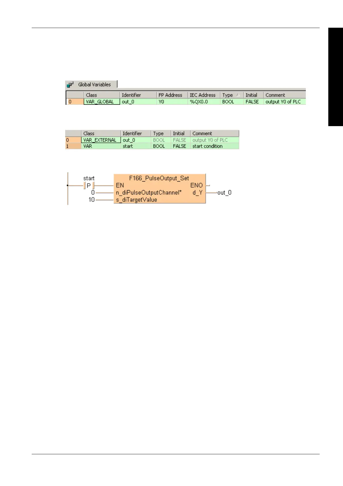
GVL
In the global variable list, you define variables that can be accessed by all POUs in the project.
POU header
All input and output variables used for programming this function have been declared in the POU
header.
Body
When the variable start is set to TRUE, the function is carried out.
LD
ST
When programming with structured text, enter the following:
IF DF(start) THEN
F166_PulseOutput_Set(n_diPulseOutputChannel := 0,
s_diTargetValue := 10,
d_Y => out_0);
END_IF;

Table of Contents

Other manuals for Panasonic FP Series

Questions and Answers:

Question and Answer IconNeed help?

Do you have a question about the Panasonic FP Series and is the answer not in the manual?

Panasonic FP Series Specifications

General IconGeneral
MountingDIN rail
TypePLC
Communication InterfaceRS-232, RS-485, Ethernet (depending on model)
Input Voltage100-240V AC or 24V DC (depending on model)
Output TypeRelay, Transistor
I/O PointsVaries by model
Operating Temperature0°C to 55°C
DimensionsVaries by model
WeightVaries by model

Related product manuals