Pulse output instructions
1035
Part III FP Instructions
For Relay T/C Register Constant
s_dutDataTable - - - - - - DT - - -
n_iPulseOutputChannel - - - - - - - - - dec. or hex.
No. IEC address Set If
R9007 %MX0.900.7 permanently
R9008 %MX0.900.8 for an instant
channel number or values of the data table are outside the
permissible range
initial speed < 40
initial speed > maximum speed
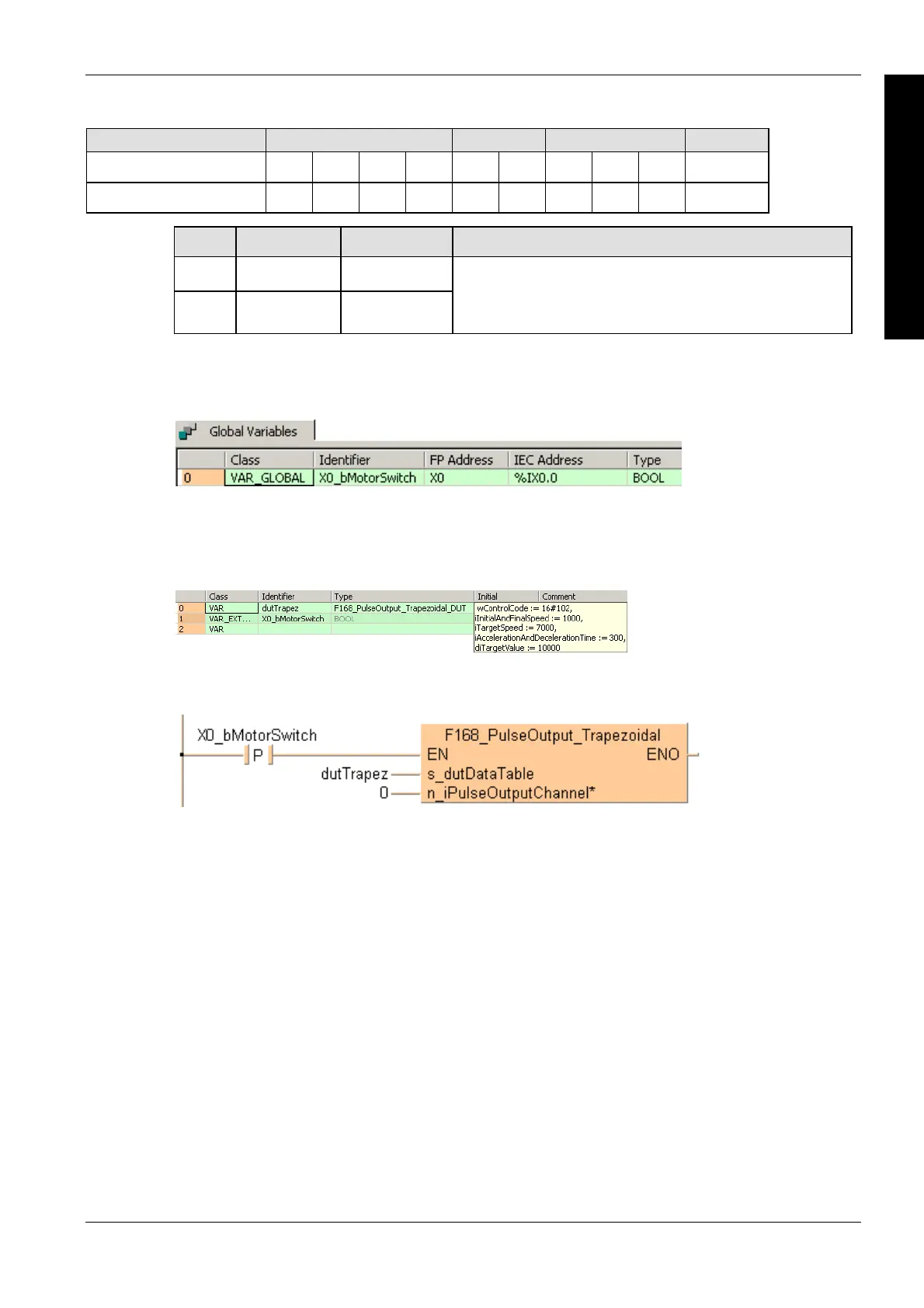
When X0_bMotorSwitch turns to TRUE the function is executed.
Error flags
Example
In this example the function has been programmed in ladder diagram (LD) and structured text (ST).
GVL
In the global variable list, you define variables that can be accessed by all POUs in the project.
DUT
The DUT F168_PulseOutput_Trapezoidal_DUT is predefined in the FP Library.
POU header
All input and output variables used for programming this function have been declared in the POU
header.
Body
LD
ST
When programming with structured text, enter the following:
IF DF(X0_bMotorSwitch) THEN
F168_PulseOutput_Trapezoidal(s_dutDataTable := dutTrapez,
n_iPulseOutputChannel := 0);
END_IF;

 Loading...


