Pulse output instructions
1072
Part III FP Instructions
For Relay T/C Register Constant
s_dutDataTable - - - - - - DT - - -
n_iPulseOutputChannel - - - - - - - - - dec. or hex.
No. IEC address Set If
R9007 %MX0.900.7 permanently
R9008 %MX0.900.8 for an instant
channel number or values of the data table are outside the permissible
range
frequency 1 is outside the permissible range
FP0R/FP-X: pulse output has not been set in the system registers
END_IF;
Operands
Error flags
Example
In this example the function is programmed in ladder diagram (LD). The same POU header is used
for all programming languages.
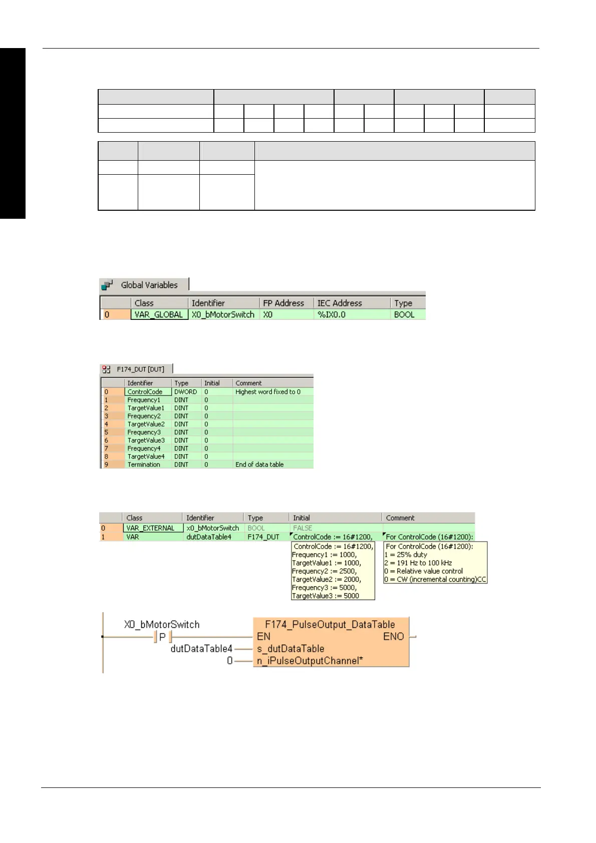
GVL
In the global variable list, you define variables that can be accessed by all POUs in the project.
DUT
The DUT F174_PulseOutput_DataTable_8_Values_DUT is predefined in the FP Library and can
be used as a sample.
POU header
All input and output variables used for programming this function have been declared in the POU
header.
LD
ST
When programming with structured text, enter the following:
IF DF(X0_bMotorSwitch) THEN
F174_PulseOutput_DataTable(s_dutDataTable := dutDataTable4, 4);

 Loading...


