Pulse output instructions
1084
Part III FP Instructions
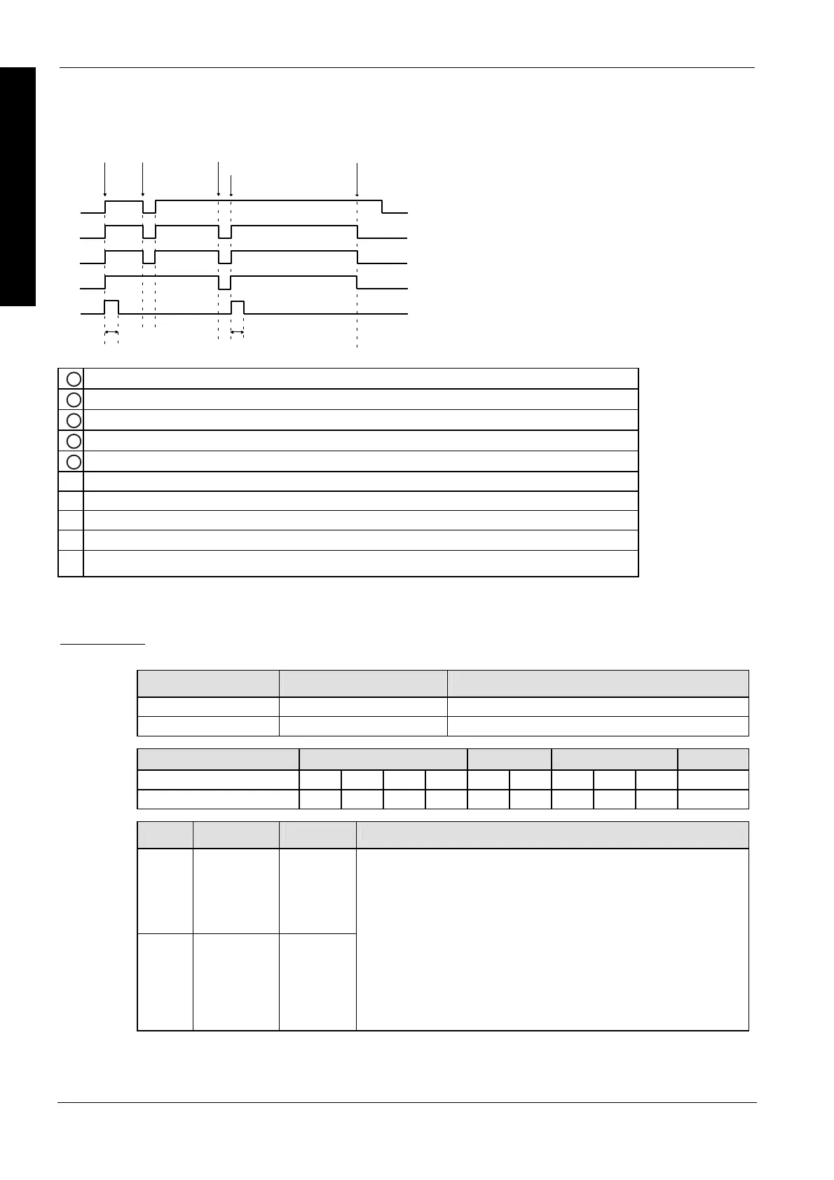
Flag setting during command execution
ab c
d
e
c
e
1
Execution condition X0
2
Pulse output control flag, channel 0 (sys_bIsPulseChannel0Active)
3
Pulse output control flag, channel 2 (sys_bIsPulseChannel2Active)
4
Circular interpolation control flag (sys_bIsCircularInterpolationActive)
5
Target value overwriting possible flag (sys_bIsCircularInterpolationOverwritingPossible)
a Start
b Execution condition FALSE
c Target value reached
d Start continue mode
e 1 scan
PLC types Availability of F176_PulseOutput_Pass (see page 1322)
Variable Data type Function
n_iPulseOutputChannel decimal constant Pulse output channel: 0, 2
s_dutDataTable F176_PulseOutput_Pass_DUT Starting address of area containing the data table
For Relay T/C Register Constant
s_dutDataTable - - - - - - DT - - -
n_iPulseOutputChannel - - - - - - - - - dec. or hex.
No. IEC address Set If
R9007 %MX0.900.7 permanently
R9008 %MX0.900.8 for an instant
channel number or values of the data table are outside the permissible
range
Relative value control: [elapsed value + target value] is outside the
range of -8388608 to +8388607
Absolute value control: target value is outside the range of-8388608 to
+8388607
start position S = end position E
start position S = pass position P
pass position P = end position E
start position S, pass position P, and end position E approximate a
straight line.
Data types
Operands
Error flags

 Loading...


