EasyManuals Logo

Panasonic FP Series User Manual

Panasonic FP Series
1345 pages
To Next Page IconTo Next Page
To Previous Page IconTo Previous Page
Page #1121 background imageLoading...
Page #1121 background image
Analog unit instructions
1120
Part IV Tool Instructions
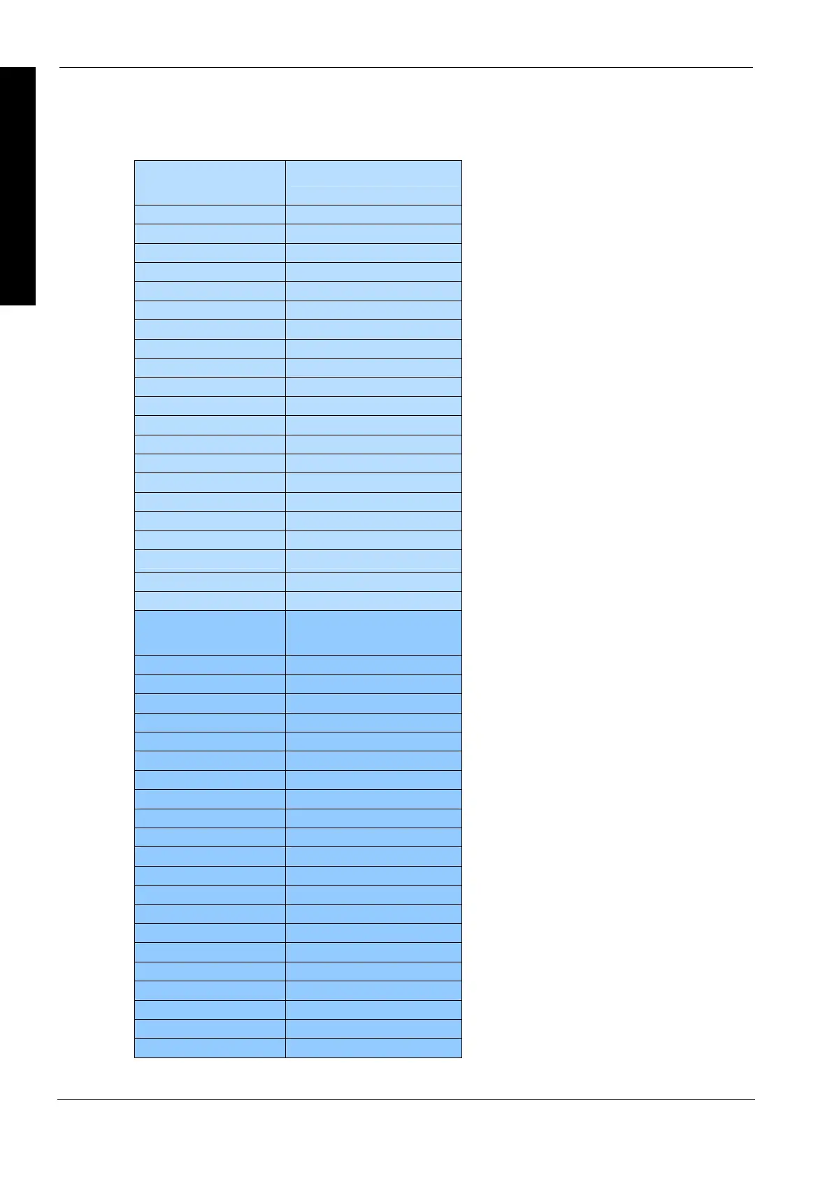
A/D conversion values
Input value (mA)
range: 0–20mA
output value
20.00 65535
19.00 62258
18.00 58982
17.00 55705
16.00 52428
15.00 49151
14.00 45875
13.00 42598
12.00 39321
11.00 36044
10.00 32768
9.00 29491
8.00 26214
7.00 22937
6.00 19661
5.00 16384
4.00 13107
3.00 9830
2.00 6554
1.00 3277
0.00 0
Input voltage (V)
range: 0.00–10.00 V
output value
10.00 65535
9.50 62258
9.00 58982
8.50 55705
8.00 52428
7.50 49151
7.00 45875
6.50 42598
6.00 39321
5.50 36044
5.00 32768
4.50 29491
4.00 26214
3.50 22937
3.00 19661
2.50 16384
2.00 13107
3.00 9830
2.00 6554
1.00 3277
0.00 0

Table of Contents

Other manuals for Panasonic FP Series

Questions and Answers:

Question and Answer IconNeed help?

Do you have a question about the Panasonic FP Series and is the answer not in the manual?

Panasonic FP Series Specifications

General IconGeneral
MountingDIN rail
TypePLC
Communication InterfaceRS-232, RS-485, Ethernet (depending on model)
Input Voltage100-240V AC or 24V DC (depending on model)
Output TypeRelay, Transistor
I/O PointsVaries by model
Operating Temperature0°C to 55°C
DimensionsVaries by model
WeightVaries by model

Related product manuals