Pulse output instructions
1188
Part IV Tool Instructions
Example
In this example the function has been programmed in ladder diagram (LD). Please refer to the
online help for a structured text (ST) example. The same POU header is used for all programming
languages.
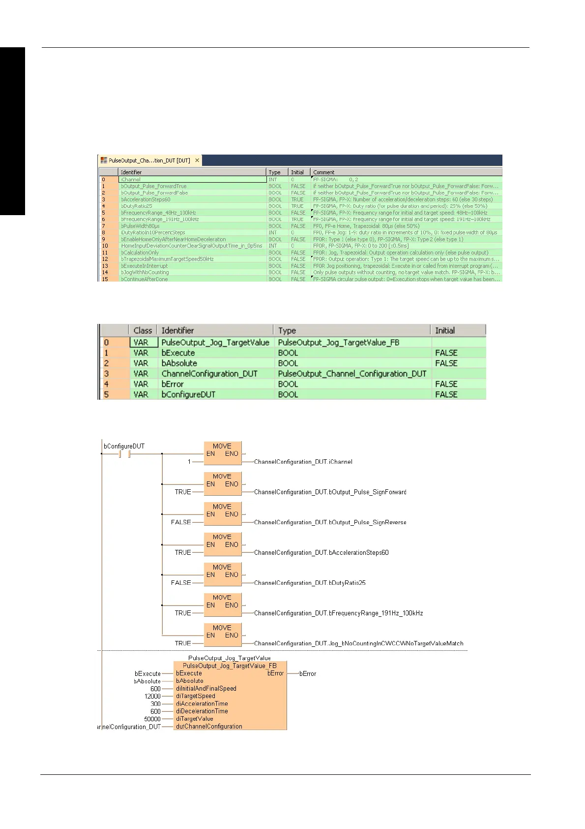
DUT
Use the following predefined DUT: PulseOutput_Channel_Configuration_DUT
POU header
All input and output variables used for programming this function have been declared in the POU
header.
Body
LD

 Loading...


