Appendix Programming Information
1271
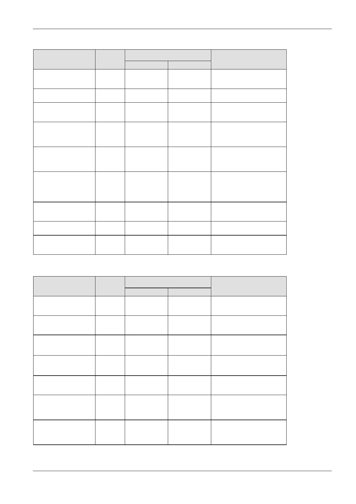
Available address area Type Memory
size
F/P IEC
Function
Internal relays 887 WR0–WR252 %MW0.0–
%MW0.252
Code for specifying 16 internal
relays as one word (16 bits) of
data.
Link relays 640 WL0–WL127 %MW7.0–
%MW7.127
Code for specifying 16 link relays
as one word (16 bits) of data.
Data registers
1)
10240 DT0–DT5999 %MW5.0–
%MW5.5999
Data memory used in a program.
Data is handled in 16-bit units
(one word).
Link registers
1)
8448 LD0–LD255 %MW8.0–
%MW8.255
Data memory shared by multiple
PLCs connected using PLC link.
Data is handled in 16-bit units
(one word)..
Timer/counter set value
area
1)
3072 SV0–SV1023 %MW3.0–
%MW3.1023
Data memory for storing the set
values of timers or counters. The
values are stored by
timer/counter number.
Timer/counter elapsed
value area
1)
3072 EV0–EV1023 %MW4.0–
%MW4.1023
Data memory for storing the
elapsed values during operation
of timers or counters. The values
are stored by timer/counter
number.
File registers
1)
32765 FL0–FL32764 %MW9.0–
%MW9.32764
Data is handled in 16-bit units
(one word). Data memory used
in a program.
Special data registers 512 DT90000–
DT90511
%MW5.90000–
%MW5.90511
Data memory for storing settings
and error codes.
Index registers 14 I0–ID %MW6.0–
%MW6.13
Data memory used to modify
constants and memory area
addresses.
Memory area [double words]
Available address area Type Memory
size
F/P IEC
Function
External input relays
1)
256 DWX0–DWX510 %ID0–
%ID510
Code for specifying 32 external
input points as a double word (32
bits) of data.
External output relays
1)
256 DWY0–DWY510 %QD0–
%QD510
Code for specifying 32 external
output points as a double word
(32 bits) of data.
Internal relays
2)
443 DWR0–DWR885 %MD0.0–
%MD0.885
Code for specifying 32 internal
relay points as a double word (32
bits) of data.
Link relays 320 DWL0–DWL638 %MD7.0–
%MD7.638
Code for specifying 32 link relay
points as a double word (32 bits)
of data.
Data registers
2)
5120 DDT0–
DDT10238
%MD5.0–
%MD5.10238
Data memory used in a program.
Data is handled in 32-bit units
(double word).
Link registers
2)
4224 DLD0–DLD8446 %MD8.0–
%MD8.8446
Data memory shared by multiple
PLCs connected using PLC link.
Data is handled in 32-bit units
(double word).
Timer/counter set value
area
2)
1513 DSV0–DSV3070 %MD3.0–
%MD3.3070
Data memory for storing the set
values of timers or counters. The
values are stored by
timer/counter number.

 Loading...


