EasyManuals Logo

Panasonic FP Series User Manual

Panasonic FP Series
1345 pages
To Next Page IconTo Next Page
To Previous Page IconTo Previous Page
Page #310 background imageLoading...
Page #310 background image
Bistable instructions
309
Part II IEC Instructions
POU header
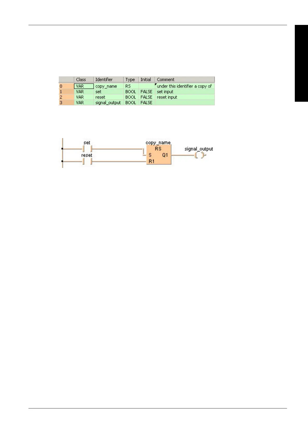
All input and output variables which are used for programming the function block RS are declared
in the POU header. This also includes the function block (FB) itself. By declaring the FB you create
a copy of the original FB. This copy is saved under copy_name, and a separate data area is
reserved.
Body
If set is set (status = TRUE) the signal_output will be set. If only reset is set, the signal_output
will be reset (status = FALSE). If both set and reset are set, the signal_output will be reset to
FALSE.
LD
ST
When programming with structured text, enter the following:
copy_name( SET:= set, RESET:= reset);
signal_output:= signal_output;

Table of Contents

Other manuals for Panasonic FP Series

Questions and Answers:

Question and Answer IconNeed help?

Do you have a question about the Panasonic FP Series and is the answer not in the manual?

Panasonic FP Series Specifications

General IconGeneral
MountingDIN rail
TypePLC
Communication InterfaceRS-232, RS-485, Ethernet (depending on model)
Input Voltage100-240V AC or 24V DC (depending on model)
Output TypeRelay, Transistor
I/O PointsVaries by model
Operating Temperature0°C to 55°C
DimensionsVaries by model
WeightVaries by model

Related product manuals