Counter instructions
321
Part II IEC Instructions
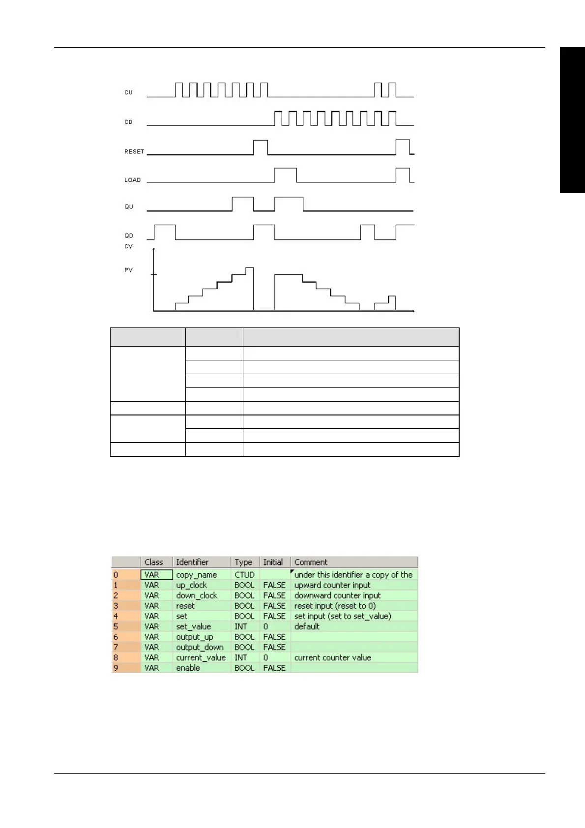
Time chart
Data type I/O Function
input CU count up
input CD count down
input RESET resets CV if set
BOOL
input LOAD loads PV to CV
INT input PV set value
output QU signal output count up
BOOL
output QD signal output count down
INT output CV current value
Data types
Example
In this example, the same POU header is used for all programming languages. For an example
using IL (instruction list), please refer to the online help.
POU header
All input and output variables which are used for programming the function block CTUD are
declared in the POU header. This also includes the function block (FB) itself. By declaring the FB
you create a copy of the original FB. This copy is saved under copy_name. A separate data area
is reserved for this copy.

 Loading...


