Timer instructions
327
Part II IEC Instructions
Data type I/O Function
BOOL (IN) input internal timer starts at rising edge
TIME (PT) input switch on delay
BOOL (Q) output signal output set if PT = ET
TIME (ET) output elapsed time
Data types
Example
In this example, the same POU header is used for all programming languages. For an example
using IL (instruction list), please refer to the online help.
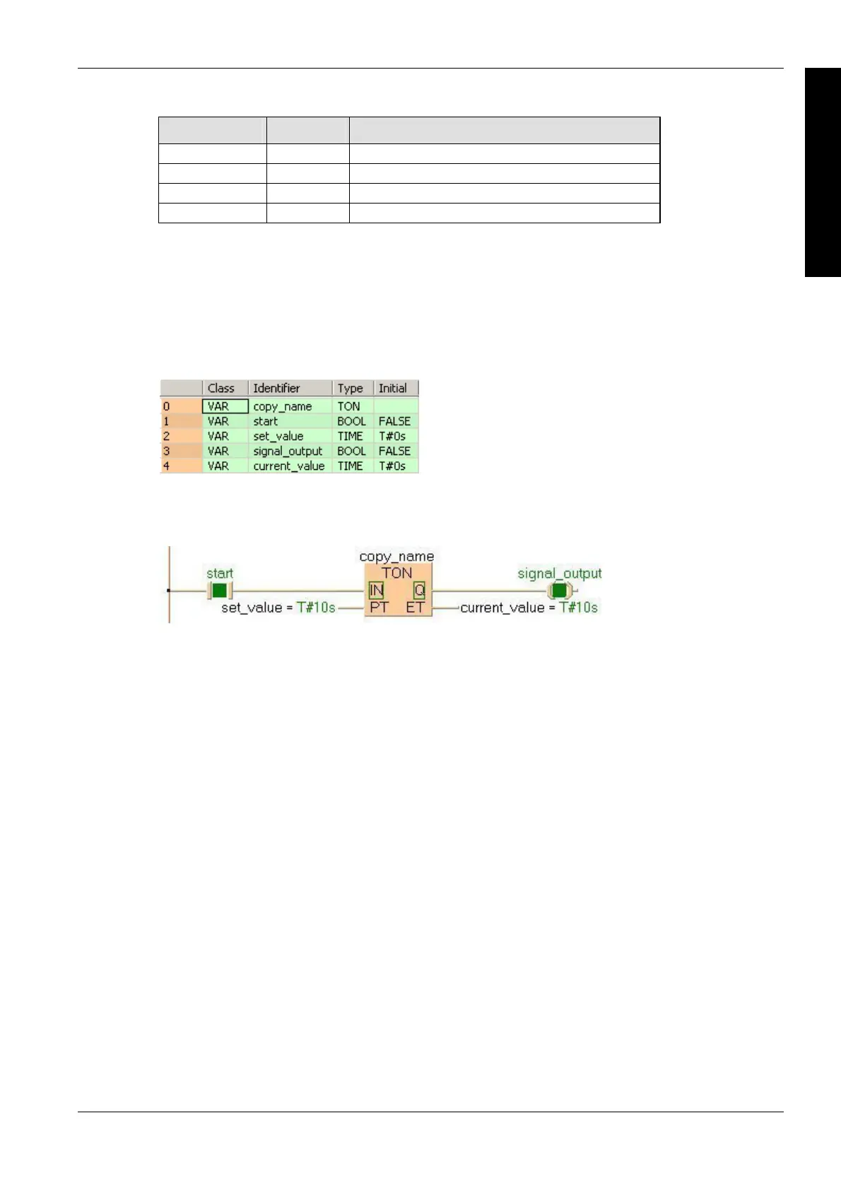
POU header
ll input and output variables which are used for programming the function block TON are declared
in the POU header. This also includes the function block (FB) itself. By declaring the FB you create
a copy of the original FB. This copy is saved under copy_name. A separate data area is reserved
for this copy.
Body
If start is set (status = TRUE), the input signal is transferred to signal_output with a delay by the
time period set_value.
LD
ST
When programming with structured text, enter the following:
copy_name( IN:= start ,
PT:= set_value ,
Q=> signal_output ,
ET=> current_value );

 Loading...


