Arithmetic instructions
434
Part III FP Instructions
No. IEC address Set If
R9007 %MX0.900.7 permanently
R9008 %MX0.900.8 for an instant
the value at s1 > s2.
R900B %MX0.900.11 TRUE the input value at s3 is 0.
In this example, the input variable input_value is declared. However, you can write a constant
directly at the input contact of the function instead.
Error flags
Example
In this example, the same POU header is used for all programming languages. For an example
using IL (instruction list), please refer to the online help.
POU header
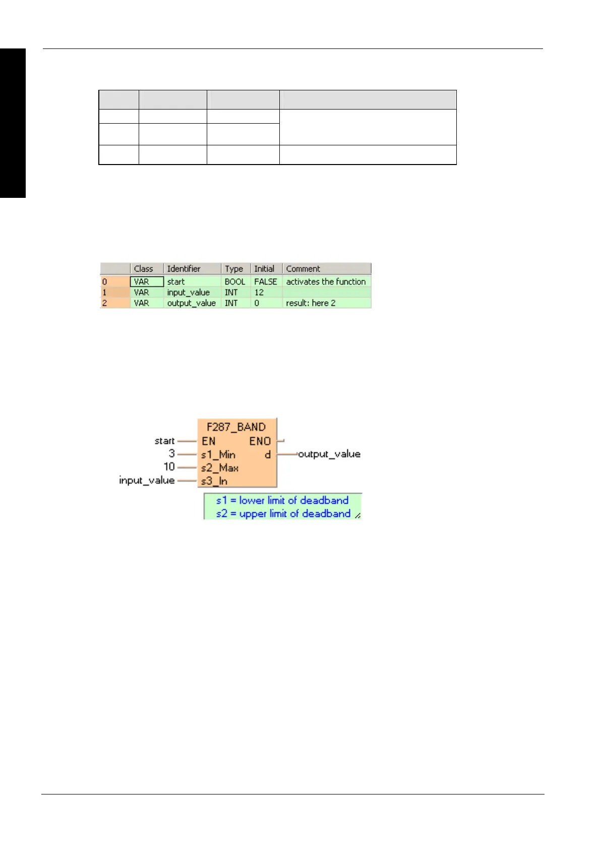
All input and output variables used for programming this function have been declared in the POU
header.
Body
When the variable start is set to TRUE, the function is carried out. The constant 3 (lower limit of
the deadband) and 10 (upper limit of the deadband) are assigned to inputs s1 and s2. However,
you can declare variables in the POU header and write them in the function in the body at the
inputs.
LD
ST
IF start THEN
F287_BAND( 3, 10, input_value, output_value);
END_IF; (* 3=lower limit of deadband, 10=upper limit of deadband *)

 Loading...


