EasyManuals Logo

Panasonic FP Series User Manual

Panasonic FP Series
1345 pages
To Next Page IconTo Next Page
To Previous Page IconTo Previous Page
Page #486 background imageLoading...
Page #486 background image
Arithmetic instructions
485
Part III FP Instructions
For Relay T/C Register Constant
n WX WY WR WL SV EV DT LD FL dec. or hex.
d1 - WY WR WL SV EV DT LD FL -
No. IEC address Set If
R9007 %MX0.900.7 permanently
R9008 %MX0.900.8 for an instant
n = 0
n > 256
The area specified by n exceeds the limit
Operands
Error flags
Example
This example illustrates the FIFO buffer by incorporating the functions F115_FIFT (see page 483),
F116_FIFR (see page 487) and F117_FIFW (see page 491). The function has been programmed
in ladder diagr
am (LD) and structured text (ST).
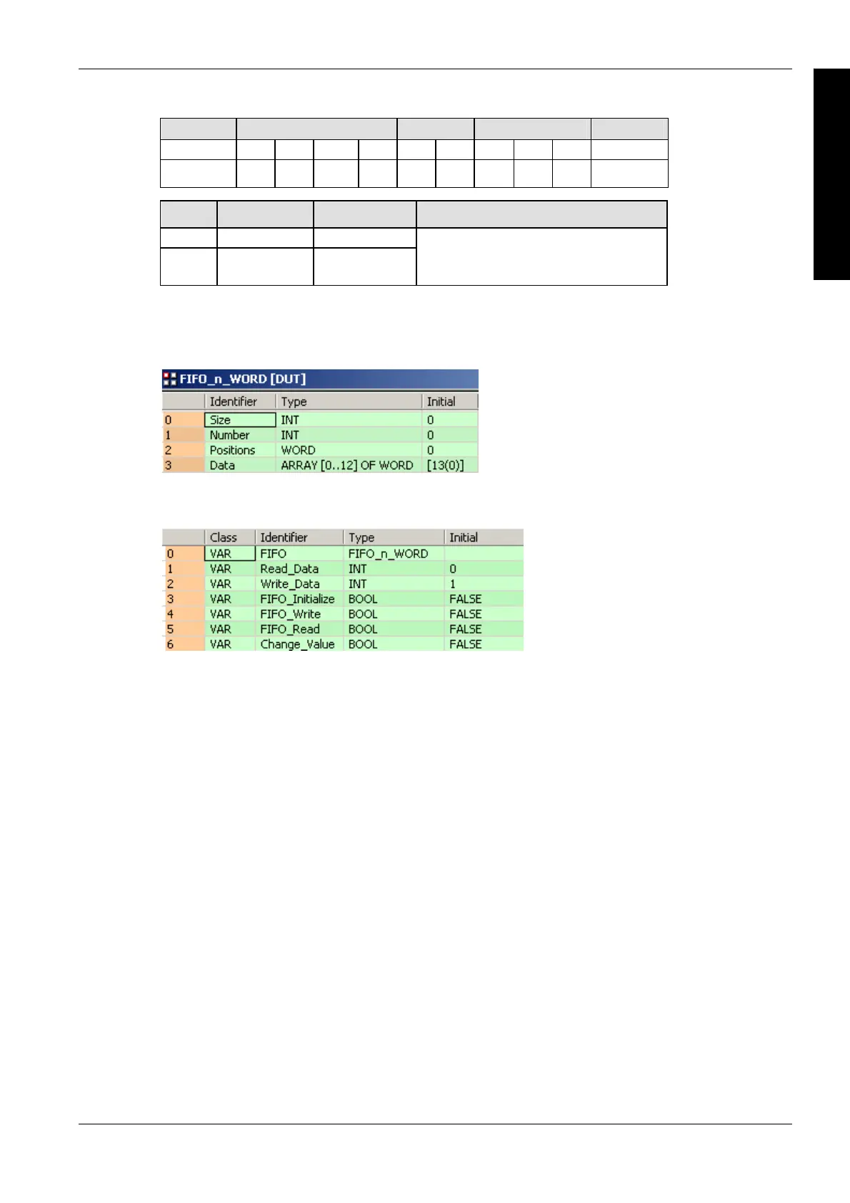
DUT
POU header
All input and output variables used for programming this function have been declared in the POU
header.

Table of Contents

Other manuals for Panasonic FP Series

Questions and Answers:

Question and Answer IconNeed help?

Do you have a question about the Panasonic FP Series and is the answer not in the manual?

Panasonic FP Series Specifications

General IconGeneral
MountingDIN rail
TypePLC
Communication InterfaceRS-232, RS-485, Ethernet (depending on model)
Input Voltage100-240V AC or 24V DC (depending on model)
Output TypeRelay, Transistor
I/O PointsVaries by model
Operating Temperature0°C to 55°C
DimensionsVaries by model
WeightVaries by model

Related product manuals