EasyManuals Logo

Panasonic FP Series User Manual

Panasonic FP Series
1345 pages
To Next Page IconTo Next Page
To Previous Page IconTo Previous Page
Page #491 background imageLoading...
Page #491 background image
Arithmetic instructions
490
Part III FP Instructions
Body
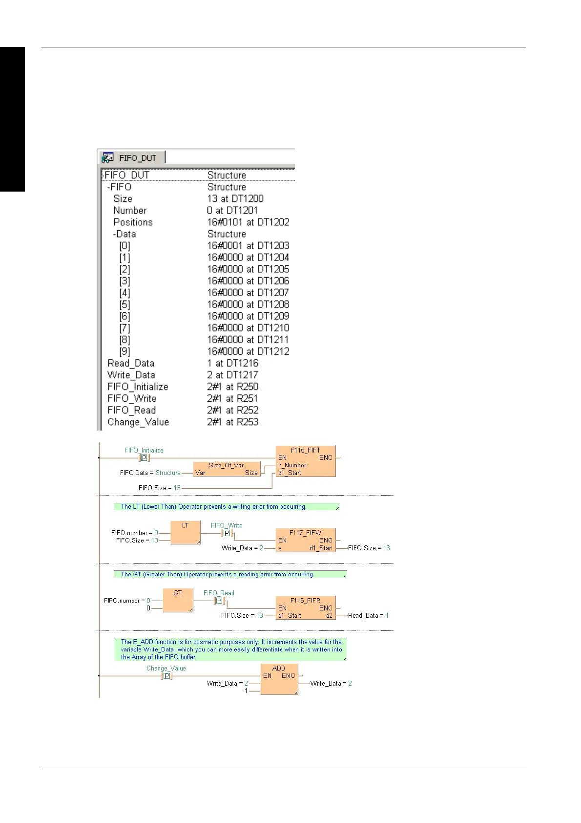
The example below illustrates the status of the buffer after FIFO_Write has been enabled twice
and FIFO_Read once. When FIFO_Write was activated the first time, the value 1 was written into
FIFO.Data[0]. When FIFO_Read was enabled, Read_Data then read this value. When
FIFO_Write was enabled the second time, the Writing pointer was incremented by one and the
value 2 written into FIFO.Data[1]. see Entry Data Monitor 1
LD

Table of Contents

Other manuals for Panasonic FP Series

Questions and Answers:

Question and Answer IconNeed help?

Do you have a question about the Panasonic FP Series and is the answer not in the manual?

Panasonic FP Series Specifications

General IconGeneral
MountingDIN rail
TypePLC
Communication InterfaceRS-232, RS-485, Ethernet (depending on model)
Input Voltage100-240V AC or 24V DC (depending on model)
Output TypeRelay, Transistor
I/O PointsVaries by model
Operating Temperature0°C to 55°C
DimensionsVaries by model
WeightVaries by model

Related product manuals