Bitwise Boolean instructions
550
Part III FP Instructions
No. IEC address Set If
R9007 %MX0.900.7 permanently
R9008 %MX0.900.8 for an instant
the area specified using the index
modifier exceeds the limit
the value at n 5 the last area for the
result exceeds the limit
Error flags
Example
In this example, the same POU header is used for all programming languages. For an example
using IL (instruction list), please refer to the online help.
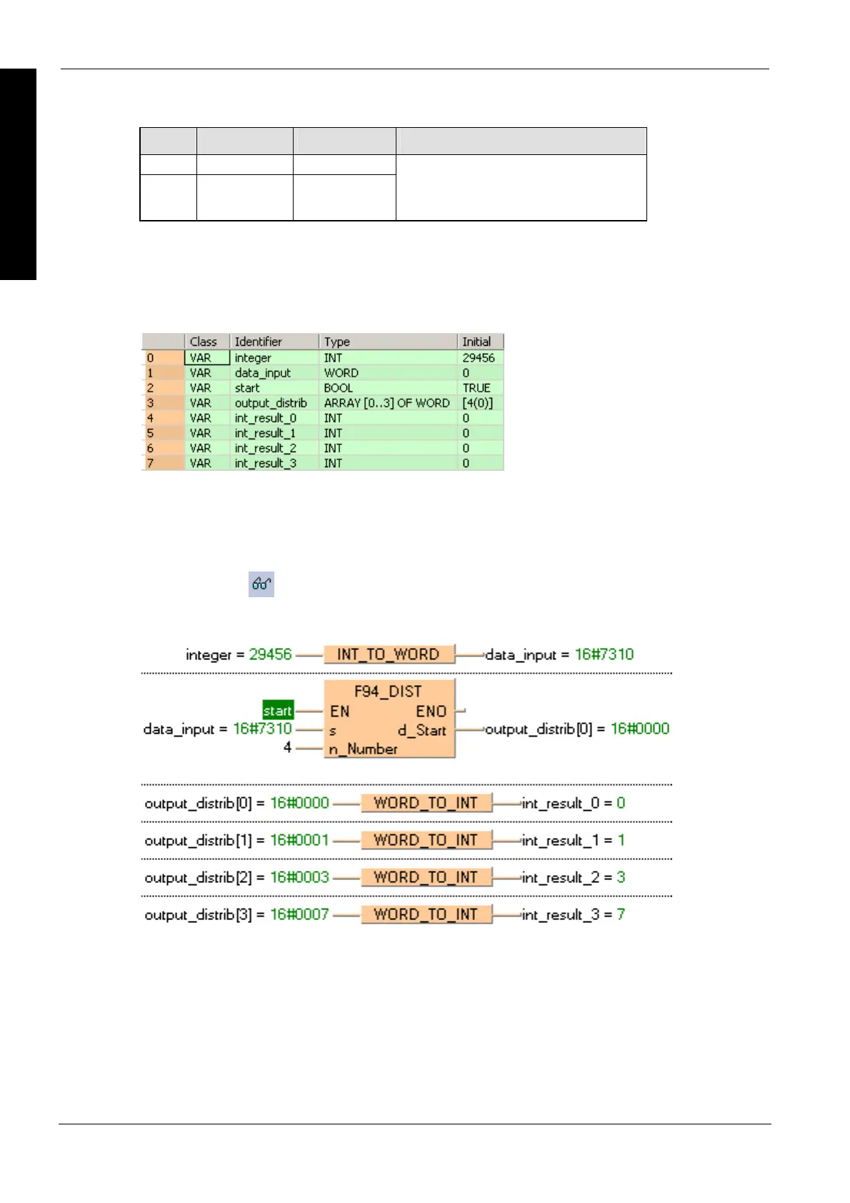
POU header
All input and output variables used for programming this function have been declared in the POU
header.
Body
When the variable start is set to TRUE, the function is carried out. The binary values in the
illustration on main help page serve as the values calculated. In this example, variables are
declared in the POU header. Also, a constant value of 4 is assigned directly at the contact pin for
n_Number.
LD
In this example, (Monitoring) was activated so you can see the results immediately.

 Loading...


