Bitwise Boolean instructions
552
Part III FP Instructions
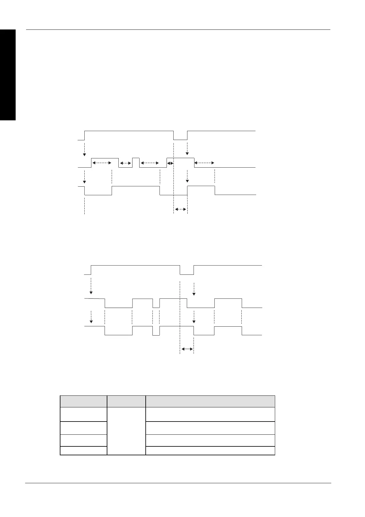
Time charts for the filter when the value assigned to s2_InputMask is 1 (16#0001), i.e. bit 0
will be filtered, the other bits will not be filtered, and the value assigned to s3_FilterTime is
500ms.
500 ms
400 ms
500 ms
200 ms
500 ms
OFF
bStart (Trigger)
ON
ON
ON
OFF
OFF
Data is initialized when the system
detects the trigger's rising edge.
Data is initialized when the system
detects the trigger's rising edge.
The instruction does not operate
while the trigger is OFF.
Bit 0 of input
data
Bit 0 of filter
result
Time chart when the value assigned to s2_InputMask is 0 (16#0000), i.e. bit 0 to F will be not
filtered
ON
ON
OFF
OFF
The instruction does not operate while
the trigger is OFF.
Data is initialized when the system
detects the trigger's rising edge.
Data is initialized when the system
detects the trigger's rising edge.
Bit 1 to 15 of
input data
Bit 1 to 15 of
filter result
bStart (Trigger)
ON
PLC types
Availability of F182_FILTER (see page 1322)
Variable Data type Function
s1_InputData Input data whose bits will be filtered according to the
input mask
s2_InputMask Input mask which specifies which bits will be filtered
s3_FilterTime Specifies the minimum off- and on-time in ms
d_OutputData
ANY16
Filtered data
Pre-
cautions
during
program-
ming
When the system detects a trigger's rising edge, all the bits of the input specified by s1_InputData
are output directly in d_OutputData and the effects of bounce are not prevented. A scan time error
may occur during filter processing, for a maximum of 1 scan.
Data types

 Loading...


