Bit-shift instructions
563
Part III FP Instructions
In the POU header, all input and output variables are declared that are used for programming this
function.
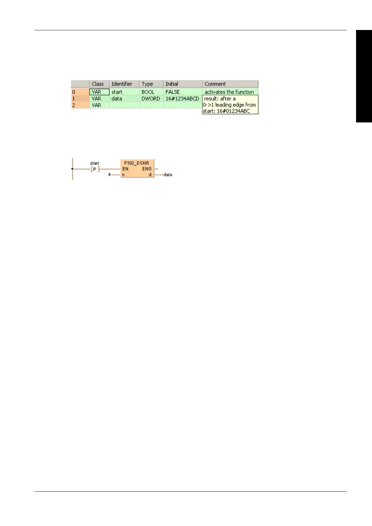
POU header
Body
When the variable start changes from FALSE to TRUE, the function is carried out. It shifts out 4
bits (corresponds to one position in a hexadecimal representation) to the right. The 4 bits in data
resulting from the shift are filled with zeros. At input n the constant 4 is assigned directly to the
function. You may, however, declare an input variable in the POU header instead.
LD
ST
When programming with structured text, enter the following:
IF DF(start) THEN
F102_DSHR( n:= 4 ,
d=> data);
END_IF;

 Loading...


