EasyManuals Logo

Panasonic FP Series User Manual

Panasonic FP Series
1345 pages
To Next Page IconTo Next Page
To Previous Page IconTo Previous Page
Page #602 background imageLoading...
Page #602 background image
Bit-shift instructions
601
Part III FP Instructions
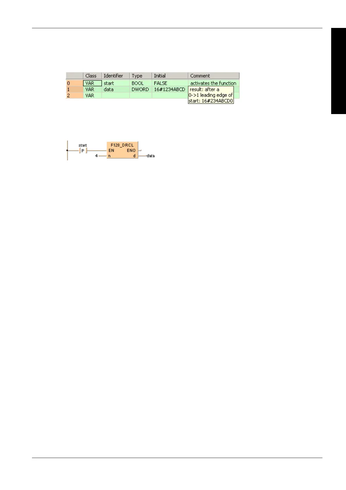
POU header
All input and output variables used for programming this function have been declared in the POU
header.
Body
When the variable start changes from FALSE to TRUE, the function is carried out. In this example
the constant (4) is assigned to the function at input n. You may, however, declare a variable in the
POU header instead.
LD
ST
When programming with structured text, enter the following:
IF DF(start) THEN
F128_DRCL( n:= 4,
d=> data);
END_IF;

Table of Contents

Other manuals for Panasonic FP Series

Questions and Answers:

Question and Answer IconNeed help?

Do you have a question about the Panasonic FP Series and is the answer not in the manual?

Panasonic FP Series Specifications

General IconGeneral
MountingDIN rail
TypePLC
Communication InterfaceRS-232, RS-485, Ethernet (depending on model)
Input Voltage100-240V AC or 24V DC (depending on model)
Output TypeRelay, Transistor
I/O PointsVaries by model
Operating Temperature0°C to 55°C
DimensionsVaries by model
WeightVaries by model

Related product manuals