Conversion instructions
642
Part III FP Instructions
This instruction also exists as a P instruction (for FP2/2SH, FP3/5, FP10/10SH PLC types), which
is only executed at the rising edge of the EN trigger. Select [Insert P instruction] from the
"Instructions" pane if you require a P instruction. To facilitate reuse, the instruction then appears
under "Recently used" in the pop-up menu. Press <Ctrl>+<Shift>+<v> within the programming
area to open the list of recently used elements.
PLC types
Availability of F77_DBIN2A (see page 1326)
Variable Data type Function
s1 ANY32 32-bit data area to be converted (source)
s2 INT specifies number of bytes to express destination data (ASCII
codes)
d WORD 16-bit area for storing ASCII codes (destination)
For Relay T/C Register Constant
s1 DWX DWY DWR DWL DSV DEV DDT DLD DFL dec. or hex.
s2 WX WY WR WL SV EV DT LD FL dec. or hex.
d - WY WR WL SV EV DT LD FL -
No. IEC address Set If
R9007
R9008
%MX0.900.7
%MX0.900.8
permanently
for an instant
the number of bytes specified by s2 exceeds
the area specified by d.
the data specified by s2 is recognized as "0".
the converted result exceeds the area
specified by d.
the number of bytes of converted result
exceeds the number of bytes specified by
s2.
Data types
Operands
Error flags
Example
In this example, the same POU header is used for all programming languages. For an example
using IL (instruction list), please refer to the online help.
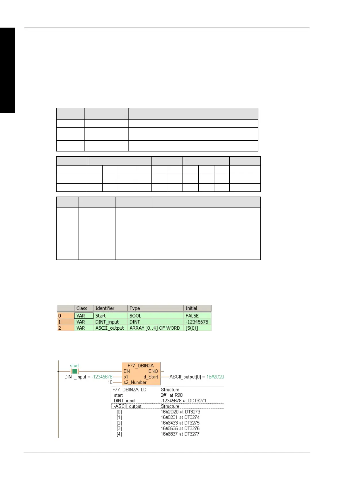
POU header
All input and output variables used for programming this function have been declared in the POU
header.
Body
When the variable start is set to TRUE, the function is carried out. The number of bytes to be
converted is entered directly at the contact pin for s2.
LD

 Loading...


