EasyManuals Logo

Panasonic FP Series User Manual

Panasonic FP Series
1345 pages
To Next Page IconTo Next Page
To Previous Page IconTo Previous Page
Page #651 background imageLoading...
Page #651 background image
Conversion instructions
650
Part III FP Instructions
Example
In this example, the same POU header is used for all programming languages. For an example
using IL (instruction list), please refer to the online help.
POU header
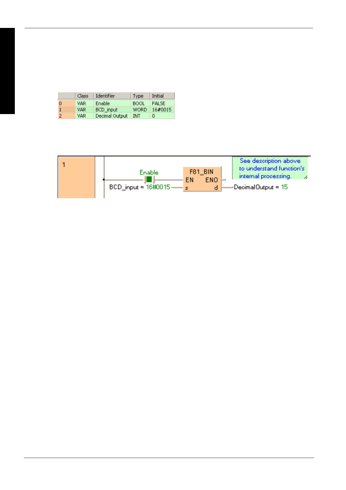
All input and output variables used for programming this function have been declared in the POU
header.
Body
When the variable Enable is set to TRUE, the function is executed. The BCD value assigned to the
variable BCD_input is converted to a decimal value and stored in the variable DecimalOutput.
The monitor value icon is activated for both the LD and IL bodies.
LD
ST
When programming with structured text, enter the following:
IF Enable THEN
F81_BIN(BCD_Input, DecimalOutput);
END_IF;

Table of Contents

Other manuals for Panasonic FP Series

Questions and Answers:

Question and Answer IconNeed help?

Do you have a question about the Panasonic FP Series and is the answer not in the manual?

Panasonic FP Series Specifications

General IconGeneral
MountingDIN rail
TypePLC
Communication InterfaceRS-232, RS-485, Ethernet (depending on model)
Input Voltage100-240V AC or 24V DC (depending on model)
Output TypeRelay, Transistor
I/O PointsVaries by model
Operating Temperature0°C to 55°C
DimensionsVaries by model
WeightVaries by model

Related product manuals