Data transfer via communication ports
722
Part III FP Instructions
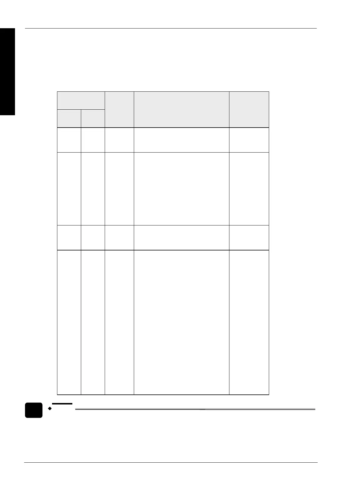
Setting the MCU's communication ports during RUN mode via the output (Y) flags
16 I/Os for Y are allocated. I/O numbers are determined depending on the installation location and
the I/O allocations of the other units.
Output signal
COM 1 COM 2
Name Description (0: OFF, 1: ON) Effective
operation
mode
Y10-Y17 Y10-Y17 Undefined Default setting: 0 (Do not change)
None
Y18 Y19 RTS signal
output
The transmission from the devices
communicating with the MCU can be
controlled by turning this output on.
Permit transmission from communicating
devices: 0
Prohibit the transmission from
communicating devices: 1
The CTS signal sent from the
communicating devices can be monitored
via X8 and X9.
Effective only
when setting the
RS/CS to be
valid and using
the
RS232C
communication
cassette.
Y1A-Y1D Y1A-Y1D Undefined Default setting: 0 (Do not change)
None
Y1E Y1F Request to
reset CH
Communication channels can be reset by
turning on Y1E or Y1F.
No request to reset: 0
Request to reset: 1
After 1 is output and the completion of the
reset is confirmed by XE/XF, return to 0.
The reset is performed only once when this
signal rises.
During reset, the following operations are
performed:
1: Transmission discontinued
2: Reception discontinued
3: Receive buffer cleared
4: Communication parameters reset
5: Error information cleared (for errors
which can be cleared)
This function can be used to delete
unnecessarily received data or to clear
errors before starting normal reception.
Program
controlled
communication
NOTE
The channel reset can be automatically performed by one of the following (in these cases, the
reset done signal by XE/YF does not turn on):
- Setting/changing communication parameters using the instruction F159_MWRT_PARA
(see page 719).

 Loading...


