Data transfer via communication ports
749
Part III FP Instructions
EXAMPLE
Receive a string of 8 bytes containing the characters "ABCDEFGH" via COM port 1. The characters are stored
in ASCII HEX code without start and end codes.
(
C
R
)
AB T UV
...
...
TRUE
FALSE
TRUE
FALSE
Reception continuedBeginning of reception
Data received
“Reception done” flag
Execution condition
Reception
possible
Reception
not possible
Reception
possible
Execution of F159_MTRN
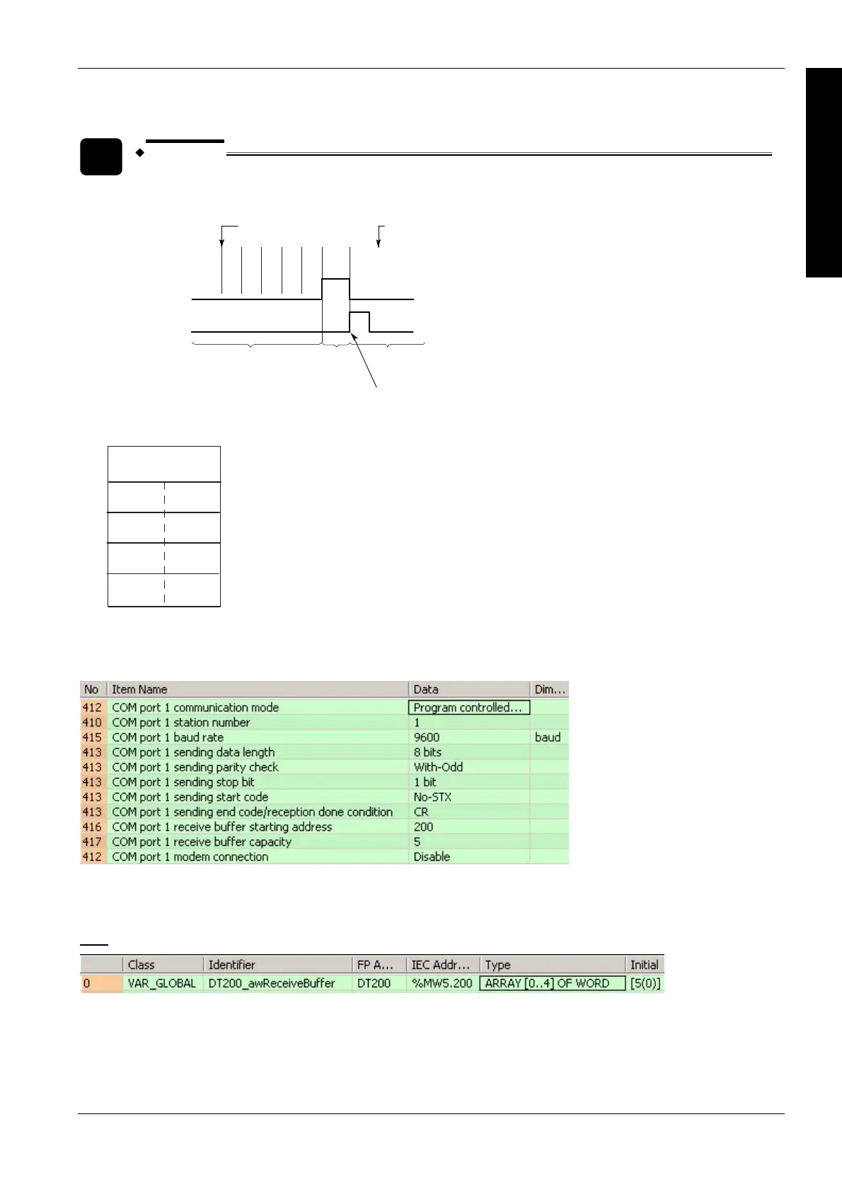
Receive buffer layout:
0
1
2
4
16#42(B) 16#41(A)
16#44(D) 16#43(C)
16#48(H) 16#47(G)
16#46(F) 16#45(E)
8
3
Offset
When reception begins, the value in offset 0 is 8. At the end of reception, the value in offset 0 is 0. The data in
offset 1 to offset 4 is received in order from the low order byte.
System register settings:
In order to use the data in the receive buffer, define a global variable having the same starting address and
capacity. In this example, the starting address is 200 (VAR_GLOBAL ReceivedData) and the receive buffer
capacity is 5 (ARRAY [0..4] OF WORD).
GVL

 Loading...


