Data transfer within the PLC
835
Part III FP Instructions
PLC type FP0 2,7k
C10/C14/C16
and FP-e
FP0 5k C32 FP0 10k
T32CP
FP-Sigma,
FP-X, FP0R
ROM EEPROM EEPROM EEPROM Flash-ROM
Block size
(1 block)
64 words
(64x16bit)
64 words
(64x16bit)
64 words
(64x16bit)
2048 words
EEPROM start
block number
0 to 9 0 to 95 0 to 255 0 to 15
Number of
blocks to be read
/ written each
execution
1 to 2 1 to 8 1 to 255 1 (writing)
1 to 16
(reading)
Write duration
(Additional scan
time)
< 20 ms each
block
< 5 ms each
block
< 5 ms each
block
< 100ms each
block
Read duration
(Additional scan
time)
Less than 1 ms
each block
Less than 1
ms each
block
Less than 1
ms each
block
9.94s +
(1562.6*numb
er of blocks)
s
Max number of
writing events
Power down,
RUN -> PROG
mode changes
are also
counted.
100,000 10,000 10,000 10,000
Max read times No limit No limit No limit No limit
PLC specific
information
Example
In this example, the same POU header is used for all programming languages. For an example
using IL (instruction list), please refer to the online help.
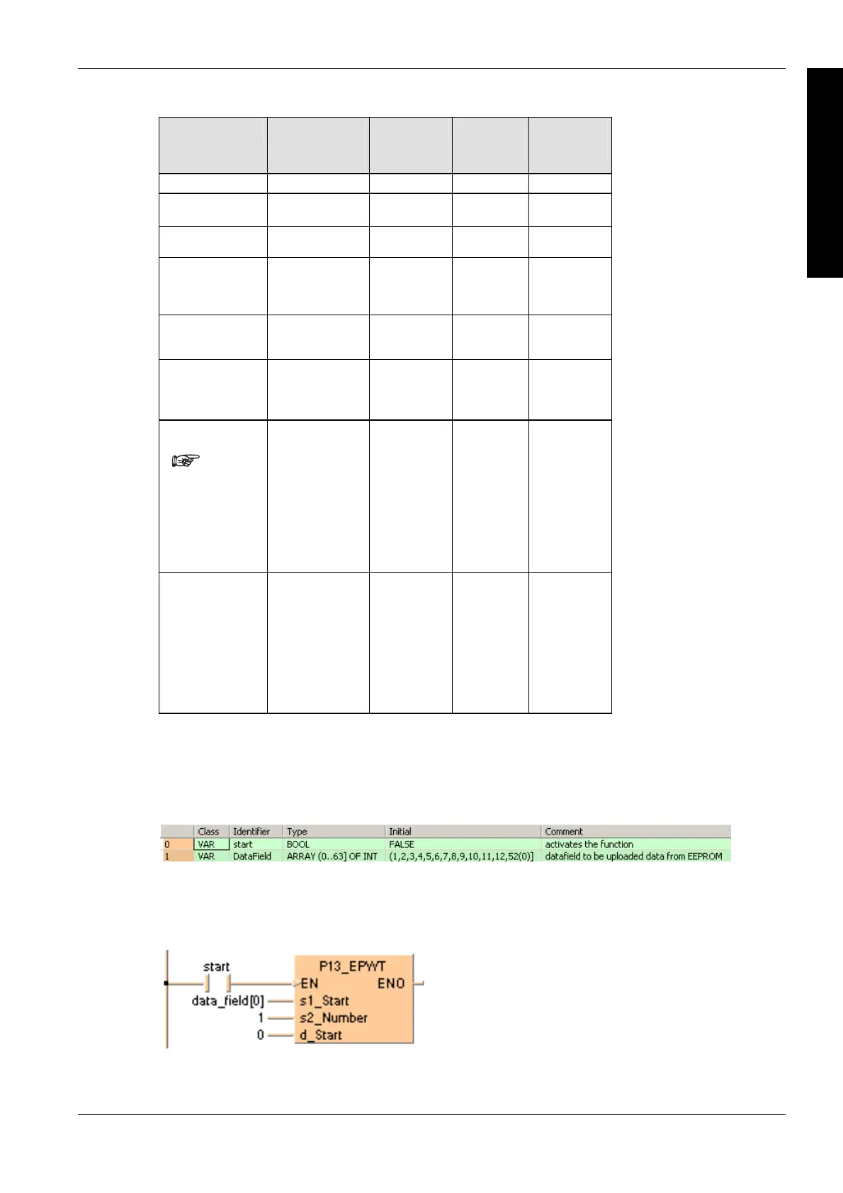
POU header
In the POU header, all input and output variables are declared that are used for programming this
function.
Body
When the variable start changes from FALSE to TRUE, the function is carried out. The function
reads the contents of data field[0] until data field[63] (s2* = 1 => 1 block = 64 words) and writes the
information after start block number 0 into the EEPROM.
LD

 Loading...


