Data transfer within the PLC
846
Part III FP Instructions
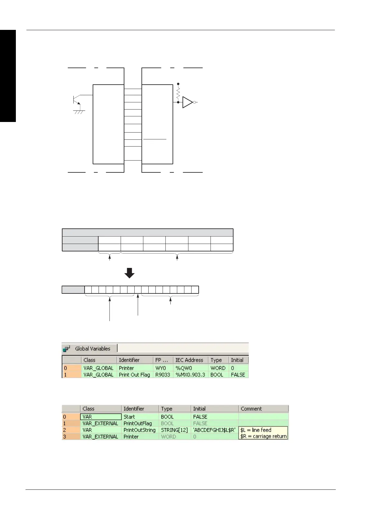
Connection example
DATA1Y0
DATA2
:
DATA3
Y1
DATA4
Y2
DATA5
Y3
Y8
DATA6
Y5
Y4
DATA7
COM
DATA8
Y6
Y7
GND
STROBE
Transistor output type
(output: 9 points or more)
Printer
(centronics interface)
The ASCII codes stored in the string PrintOutString are output through word external output relay
WY0 when trigger Start turns on.
LF J I G F E
0D 0A 4A 49 48 47 46 45
DCBA
44 43 42 41
WY0
YF YE YD YC YB YA Y9 Y8 Y7 Y6 Y5 Y4 Y3 Y2 Y1 Y0
H
C
R
PrintOutString
Source: ASCII code for 12 characters A, B, C, D, E, F, G, H, I and J
ASCII HEX code
ASCII character
Control data for printer
ASCII codes
start: ON
Destination
Y0 to YF: for data signals of printer
(Y0 to Y7 correspond to DA A1 to DA A8 of printer)
Y8: for strobe signal of printer
Y9 to YF: not used
Example
In this example the function is programmed in ladder diagram (LD). The same POU header is used
for all programming languages.
GVL
In the global variable list, you define variables that can be accessed by all POUs in the project.
POU header
All input and output variables used for programming this function have been declared in the POU
header.

 Loading...


